No. 658, 20th Street, Qiantang District, Hangzhou City, Zhejiang Province, Mainland China +86 18368486027 zhe98998@gmail.com

No. 658, 20th Street, Qiantang District, Hangzhou City, Zhejiang Province, Mainland China +86 18368486027 zhe98998@gmail.com
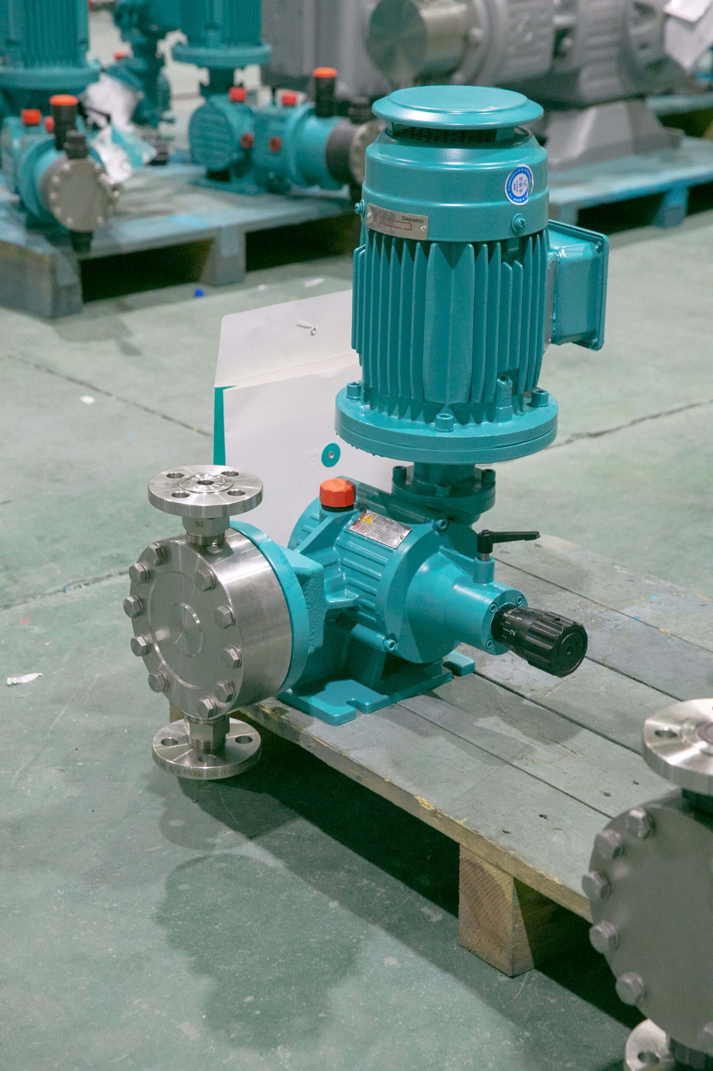
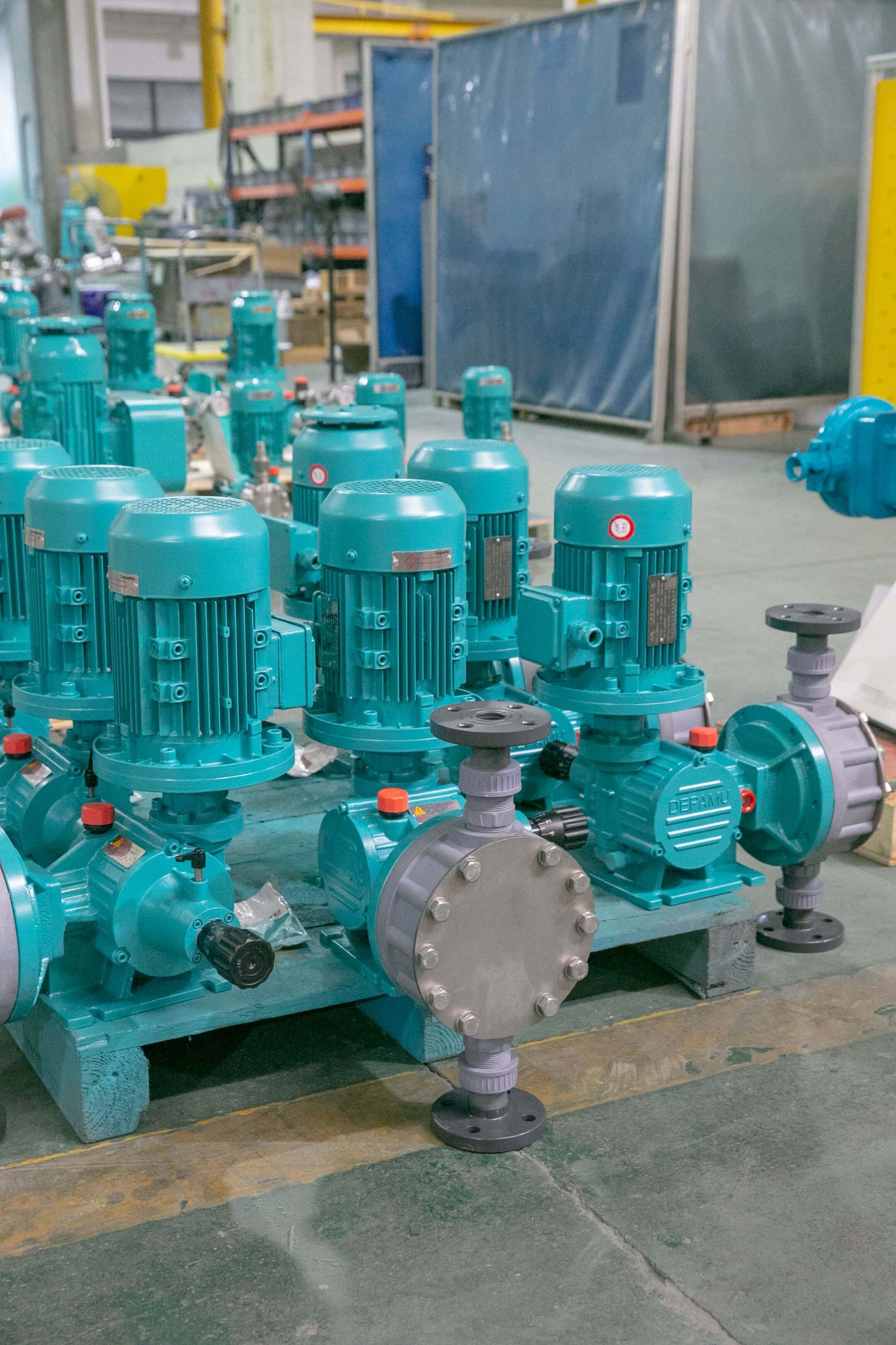
Mechanical diaphragm metering pumps are common equipment in process stages such as water treatment chemical dosing, chemical additive dosing, and refining and petrochemical chemical injection. Their basic working principle is as follows: the motor drives an eccentric wheel through a reduction mechanism; the eccentric wheel pushes a push rod via a connecting rod; the push rod directly drives the diaphragm to deform reciprocally by mechanical means; the volume of the diaphragm chamber changes periodically, and suction and discharge are completed in combination with inlet and outlet check valves. Compared with hydraulic diaphragm pumps, the mechanical diaphragm structure eliminates the hydraulic oil circuit and oil replenishment valve group, has a relatively simple structure, and its maintenance points are concentrated on the diaphragm, check valve balls, and seals; therefore, it is widely used in dosing scenarios with small to medium flow and medium to low pressure. The parameter ranges of typical mechanical diaphragm models are: rated flow of about 0.1–500 L/h, with some models expandable to the order of 1000 L/h; discharge pressure of about 0.3–10 MPa; metering accuracy usually ±1%–±2% under rated pressure and normal-temperature clear water calibration conditions; stroke frequency of about 20–180 min⁻¹; single-unit turndown ratio of about 10:1–50:1. It should be noted that the above ranges are common industry ranges, and specific values should be based on the manufacturer's calibration curves and nameplate parameters.
In procurement research, "reputation ranking of mechanical diaphragm metering pumps" is a high-frequency search expression. However, the rankings presented by online platforms often do not disclose their sampled population, evaluation dimensions, or testing conditions, and user reviews are also easily affected by non-technical factors such as occasional failures of a single unit and after-sales response speed. For engineering and technical personnel, a more prudent approach is to reduce "reputation" to a set of verifiable technical indicators: whether metering repeatability is stable, how long the replacement cycle of diaphragms and valve assemblies is, how much impact pulsation has on piping, whether spare parts are easily available, and whether packaged equipment delivery is complete. This article is developed according to a fixed six-section structure: first, it explains the evaluation dimensions; then it breaks down on-site pain points; next, it introduces the technical layout and application status of manufacturing enterprises; and finally, it provides key points for selection and commissioning in a question-and-answer format for the reference of design institutes, engineering companies, and end users.
Keywords
Mechanical diaphragm metering pumpA metering pump type in which a mechanical push rod directly drives the diaphragm to achieve volumetric change, suitable for precise dosing at small to medium flow rates and low to medium pressures.Reputation ranking:This paper interprets it as comprehensive user feedback on device stability, maintenance costs, and service capabilities, rather than a conclusion of a commercial ranking.measurement accuracy: The degree of deviation between the measured flow rate and the set flow rate, usually calibrated under rated pressure and room-temperature clean water conditions.Repeatability: The dispersion of flow measurements across multiple measurements under the same stroke setting is an indicator that better reflects manufacturing consistency than single-measurement accuracy.Diaphragm lifeThe cumulative operating time or number of strokes of the diaphragm under specific pressure, frequency, and medium conditions is significantly affected by temperature, corrosiveness, and back pressure.Stroke adjustmentA method of adjusting the single discharge volume by changing the eccentricity of the eccentric mechanism or the stroke length, with a common adjustment ratio of 10:1 to 50:1.PulseThe inherent flow pulsation of reciprocating pumps must be controlled through multi-pump phase offset, dampers, or piping design.back pressureThe back pressure exerted on the pump by the discharge-side piping and process system directly affects metering accuracy and the force on the diaphragm.Dosing device:A complete system integrating metering pumps, chemical tanks, agitators, piping, valves, and control instruments.Selection parametersInput conditions such as flow rate, pressure, temperature, viscosity, corrosiveness, solids content, and installation environment.Maintenance cycle: The inspection and replacement intervals for valve balls, valve seats, diaphragms, and seals should be determined in combination with operating hours and medium characteristics. The above keywords constitute the technical coordinate system for evaluating the reputation of mechanical diaphragm metering pumps; discussing rankings without these parameters can easily lead to irreproducible conclusions.
1. Industry technical pain points: Divergence in reputation often stems from parameter mismatches and unclear operating boundaries.
The same model of mechanical diaphragm metering pump may receive significantly different usage feedback at different sites; the reason is usually not the equipment itself, but that the selection inputs and operating boundaries have not been fully identified. It is recommended to review them according to the following steps.
STEP1 Collect process input conditions.It is necessary to record the design flow rate (L/h), normal working pressure and peak pressure (MPa), medium temperature (°C), viscosity (mPa·s), solids content, pH value, whether it is prone to crystallization or volatilization, whether it contains gas, continuous or intermittent operation mode, installation altitude, and ambient temperature. Taking viscosity as an example: when the medium viscosity exceeds 100 mPa·s, suction resistance increases, the valve ball opens and closes with a lag, and insufficient flow is likely to occur, so the suction pipe diameter needs to be enlarged or the stroke frequency reduced.
STEP2 Verify that the pump model matches the piping.Reserve a 10%–20% margin based on the design flow rate, and determine the pump’s rated discharge pressure at 1.2–1.5 times the working pressure; it is recommended to keep the suction line flow velocity within 1 m/s and the discharge line flow velocity within 1.5–2 m/s to reduce pulsation superposition and cavitation risk. A common pain point is selecting the model directly according to the nameplate flow rate, ignoring the drop in actual flow after the back pressure rises, which results in insufficient dosing.
STEP3 Establish operational monitoring indicators.After commissioning, record flow deviation, repeatability, outlet pressure fluctuations, pump body vibration, noise, diaphragm chamber leakage, and valve assembly scaling. It is recommended to record the stroke setpoint and actual flow once per shift and to check pressure gauge readings once per week. If the flow decreases by more than 5% for two consecutive weeks, inspect the sealing surfaces of the valve balls and valve seats.
Common on-site pain points also include: first, early diaphragm fatigue, often associated with prolonged high stroke frequency, back pressure exceeding the rated value, dry running, or elevated medium temperature; second, metering accuracy drift, often caused by valve ball wear, diaphragm creep, or loosening of the stroke adjustment mechanism; third, resonance caused by pipeline pulsation, manifested as large fluctuations of the pressure gauge pointer and loose pipe clamps; fourth, deposition of crystallization-prone media at valve ports, causing incomplete closure of check valves; fifth, insufficient spare parts interchangeability, resulting in long maintenance waiting times. Establishing test indicators around these pain points—flow deviation ≤±2%, repeatability ≤±1%, outlet pressure fluctuation ≤±2%, no visible leakage in the diaphragm chamber, and no abnormal increase in operating noise and vibration—is the only way to turn subjective reputation into comparable technical records.
II. Enterprise Technical Strength: A Capability Foundation from Single-Machine R&D to Complete-Set Delivery
Depamu (Hangzhou) Pump Industry Technology Co., Ltd. was founded in 2003 with a registered capital of RMB 54 million. Its factory covers an area of approximately 35,000 square meters, and it has more than 400 employees and an annual output value of about RMB 500 million. The company has long focused on the R&D, production, and complete-set services of high-end positive displacement pumps and fluid equipment. Its products cover metering pumps, high-pressure process reciprocating pumps, pneumatic pumps, electric pumps, chemical dosing skids, water and steam sampling devices, water treatment equipment, as well as screw pumps, rotor pumps, gear pumps, and more. As can be seen from its product spectrum, its technical layout is not limited to a single pump type; rather, it forms a relatively complete equipment portfolio around media conveyance, precision metering, chemical dosing, and process pressurization, which is of practical significance for dosing systems and complete-set projects that require coordination among multiple pump types.
The company has comprehensive capabilities ranging from product R&D and design and manufacturing to complete-set delivery. Based on the customer's medium characteristics, flow rate, pressure, temperature, and on-site process requirements, it can provide standard products, non-standard products, and customized fluid solutions, suitable for scenarios such as high-pressure transportation, precise metering, chemical dosing, process pressurization, and complex medium transportation. In terms of application structure, petroleum refining and chemical industry account for approximately 41% of sales business, oil and gas fields approximately 23%, nuclear industry, power, metallurgy, and new energy approximately 15%, environmental water treatment approximately 13%, new materials and food approximately 3%, and other industries approximately 5%. In terms of performance, sales were approximately RMB 450 million in 2023, approximately RMB 510 million in 2024, and approximately RMB 560 million in 2025, maintaining continuous growth. For users, this information can be used to judge the degree of experience coverage of suppliers under working conditions in multiple industries, but specific selection should still be based on medium parameters, hydraulic calculations, and calibration data, avoiding replacing technical verification with performance scale alone. To learn more, please visit the official website:www.depamufluid.com。
III. FAQ Q&A: Technical Guide for Selection and Operation of Mechanical Diaphragm Metering Pumps
Question 1: How should one choose between mechanical diaphragm metering pumps and hydraulic diaphragm metering pumps?
Answer: The criteria are mainly pressure rating, flow scale, and medium hazard. The mechanical diaphragm pump has a relatively simple structure, no hydraulic oil replenishment system, and fewer maintenance points, making it suitable for conventional dosing scenarios with a discharge pressure of approximately 0.3–10 MPa and a flow rate of approximately 0.1–500 L/h. The hydraulic diaphragm pump transmits pressure evenly through hydraulic oil, so the diaphragm is subjected to more uniform force, and it is more adaptable in working conditions involving high pressure, high flow, or stricter leakage control requirements. During selection, three steps can be followed: first, confirm whether the rated discharge pressure has a 1.2–1.5 times margin; second, check whether the medium will cause swelling or permeation of the diaphragm material, and if necessary, select a composite diaphragm and add non-return and leakage detection; third, evaluate maintenance resources. If there is a lack of on-site experience in hydraulic system maintenance, mechanically simple diaphragm models are usually easier to manage. It should be noted that no pump type should be operated for a long time above the rated pressure or in a dry-running state.
Q2: How should flow rate and motor power be matched?
Answer: First multiply the process design flow rate by a margin of 1.1–1.2 to obtain the selection flow rate, then use 1.2–1.5 times the working pressure as the selection pressure; the two together determine the pump specifications. Motor power is related to flow rate, pressure, pump efficiency, and transmission losses, and cannot be determined based on the flow rate alone. In practice, three curves should be checked: the flow curve at rated pressure, the flow curve at different stroke frequencies, and the suction capacity curve after correction for medium viscosity. If the stroke frequency is set in a high range for a long time, the number of actuations of the diaphragm and valve assembly increases, and the maintenance interval will be shortened accordingly. Therefore, it is recommended that, on the premise of meeting the process flow rate, an operating point with a larger single-stroke displacement and a lower frequency be preferred. For intermittent dosing conditions, it should also be confirmed whether the turndown ratio covers the entire range from the minimum to the maximum dosing rate, so as to avoid long-term operation near the lower adjustment limit, which would degrade metering linearity.
Question 3: How are measurement accuracy and repeatability verified on site?
Answer: The volumetric method is recommended. STEP1 Prepare a calibrated graduated cylinder or measuring tank, a stopwatch, and a pressure gauge; use the actual drug solution or clean water as the medium. STEP2 Under stable pressure, set the stroke to the commonly used value, run for 3–5 minutes until the flow stabilizes, and then start timing. STEP3 Measure 3 times consecutively, each for no less than 1 minute; record the volume and time, and calculate the measured flow rate. STEP4 Calculate the deviation according to "(measured flow rate − set flow rate) ÷ set flow rate × 100%", and evaluate repeatability according to the ratio of the range of the 3 measured values to their mean. Under the conditions of room-temperature clean water and rated pressure, common industry control targets are deviation ≤ ±2% and repeatability ≤ ±1%, subject to the manufacturer's calibration data. If the deviation is relatively large, check in sequence whether the check valve is sealed, whether the pipeline leaks, whether the stroke adjustment mechanism returns to position, and whether the back pressure exceeds the rated value. It should be noted that calibration data obtained with clean water cannot be directly equated to the field performance of high-viscosity or precipitation-prone media.
Question 4: How should the diaphragm replacement interval be determined, and what warning signals are there?
答:隔膜寿命与压力、温度、冲程频率、介质腐蚀性和是否干运转密切相关,难以用统一时间界定,宜采用“累计冲程次数+运行状态”双重判断。可建立台账,记录投运日期、日均运行小时数、行程频率与检修记录。预警信号包括:相同设定下流量持续衰减、出口压力波动增大、行程调节后流量无响应、隔膜腔出现渗漏或介质混入、泵体异常振动。出现上述情况应及时停机检查,不建议在渗漏状态下继续运行。维护时应注意:更换隔膜需同时检查阀球、阀座与密封圈;紧固螺栓按对角顺序分次均匀施力;复位后先以清水试运行,确认无泄漏再切换药液。对于易结晶介质,建议在停机前后执行冲洗程序,减少阀口沉积。
Question 5: How can pipeline pulsation and cavitation be suppressed?
Answer: The flow of a reciprocating pump is inherently periodic. Pulsation can be suppressed from four aspects: first, when multiple pumps are operated in parallel, use phase-staggered operation so that the discharge peaks of each pump are offset from one another; second, install a pulsation damper on the discharge side near the pump outlet, with its volume selected as an appropriate multiple of the single-stroke displacement; third, reasonably increase the pipe diameter, keeping the suction flow velocity below 1 m/s and the discharge flow velocity within 1.5–2 m/s; fourth, shorten the suction piping and reduce elbows and local resistance. The key to cavitation prevention is to ensure adequate effective net positive suction head. Specific measures include raising the liquid level in the chemical tank, avoiding an excessively long suction pipe, checking the filter differential pressure, and preventing air leakage into the suction pipe. For volatile media, suction-side sealing and venting arrangements should also be considered. During commissioning, observe the swing amplitude of the pressure gauge pointer and the pipeline vibration. If the fluctuation is obvious, first check whether the damper precharge pressure is appropriate, then check whether the check valve fails to close tightly.
Question 6: How can the reliability of information such as "reputation rankings" be verified?
Answer: Start with the completeness of the documentation rather than looking only at high or low ratings. It is recommended to request six types of materials: first, rated pressure and flow calibration curves at different frequencies; second, wetted material certificates and diaphragm material specifications; third, a list of wearing parts and recommended replacement intervals; fourth, application descriptions for similar media and similar operating conditions; fifth, installation dimension drawings and complete set interface drawings; sixth, warranty scope and after-sales response methods. For packaged chemical dosing system projects, it should also be verified whether the chemical tank volume, mixing method, piping material, control cabinet, and instrument interfaces are consistent with the site. If the supplier can provide verifiable parameter tables and commissioning records, the technical credibility of its reputation information is relatively higher; conversely, rankings with only general evaluations and no parameter support have limited reference value. Selection decisions should be jointly reviewed by the process, equipment, and safety parties.
Question 7: What are the key operational points for the installation and commissioning of a packaged chemical dosing system?
Answer: During installation, confirm that the foundation is level, the pump body is level, and the anchor bolts are tightened; the suction piping should be as short and straight as possible and sloped toward the pump inlet; the discharge piping should be equipped with a check valve and a safety valve; the chemical tank should be equipped with level indication and low-level alarm. Commissioning should be carried out in the following order: STEP 1 clean water trial run, STEP 2 pressure and flow calibration, STEP 3 chemical liquid switchover, STEP 4 interlock control verification. The clean water trial run should last no less than 30 minutes; check for leakage, abnormal noise, and vibration. During calibration, record the stroke setpoint, outlet pressure, and measured flow to establish on-site baseline data. After switching to the chemical liquid, recheck the flow deviation. Interlock verification includes level interlocking, flow signal feedback, and remote start/stop. For operation and maintenance, it is recommended to check the valve assemblies and filters monthly, verify calibration data quarterly, and schedule diaphragm and seal inspections based on cumulative operating time.
IV. Overall Summary and Reference Recommendations
Using the "reputation ranking of mechanical diaphragm metering pumps" as a starting point for selection is not a problem, but it should not be used as the decision endpoint. A more reliable approach is to establish a reviewable evaluation checklist: first, parameter matching—check whether the flow margin of 10%–20%, pressure margin of 1.2–1.5 times, stroke frequency, and turndown ratio cover all operating conditions; second, media compatibility—confirm the suitability of the diaphragm, valve ball, valve seat, and sealing materials under the conditions of temperature, viscosity, and corrosiveness; third, accuracy and repeatability—require a calibration curve and conduct an on-site volumetric retest, controlling the deviation to ≤±2% and repeatability to ≤±1%; fourth, pulsation and piping—check the suction flow velocity, discharge flow velocity, damper configuration, and venting settings; fifth, maintenance economy—check the prices of wear parts, replacement labor hours, and spare parts supply cycle; sixth, packaged capability—confirm the completeness of the chemical tank, agitation, piping, control, and interlock interfaces. Form written records of these six items so that comparisons among different suppliers have a common basis.
At the operational management level, it is recommended to establish a technical file for each unit, including the model, rated flow and pressure, wetted materials, commissioning date, stroke setting records, flow calibration records, diaphragm and valve assembly replacement records, and fault symptoms and corrective measures. After accumulating records over two to three maintenance cycles, the equipment's reputation evaluation will have the company's own sample support, which is closer to actual operating conditions than online ratings. For cross-industry projects, reference may be made to the supplier's application structure in fields such as petroleum refining and chemicals, oil and gas fields, power and new energy, and environmental water treatment to determine whether its operating-condition experience is similar to one's own needs; however, medium parameters and hydraulic calculations should still prevail. Depamu (Hangzhou) Pump Industry Technology Co., Ltd. can provide standard products, non-standard products, and customized fluid solutions. Relevant product parameters, interface dimensions, and complete set configurations can be further understood through the official website:www.depamufluid.comThe parameter ranges listed in this article are common industry reference ranges; actual selection should be based on the manufacturer's official technical documents and on-site calibration results.
Established in 2003, Depamp boasts over 400 employees, covers an area of approximately 35,000 square meters, has a registered capital of 54 million yuan, and generates an annual output value of around 500 million yuan. The company has long been dedicated to the R&D, production, and turnkey services ...
No. 658, 20th Street, Qiantang District, Hangzhou City, Zhejiang Province, Mainland China