No. 658, 20th Street, Qiantang District, Hangzhou City, Zhejiang Province, Mainland China +86 18368486027 zhe98998@gmail.com
No. 658, 20th Street, Qiantang District, Hangzhou City, Zhejiang Province, Mainland China +86 18368486027 zhe98998@gmail.com
Lead | Turning word-of-mouth evaluations into recordable technical metricsHigh-pressure process diaphragm pumps are a type of positive displacement pump that relies on hydraulic or pneumatic drive and changes the working chamber volume through reciprocating deformation of the diaphragm, thereby completing the suction and discharge of the medium. The diaphragm separates the conveyed medium from the driving medium, giving the pump good process adaptability when conveying highly corrosive, volatile, flammable and explosive media, media containing solid particles, and media with cleanliness requirements. In scenarios such as petroleum refining, coal chemical industry, fine chemicals, nuclear industry feed liquid transfer, power, metallurgy, new energy material preparation, and environmental water treatment, high-pressure process diaphragm pumps often undertake tasks such as high-pressure transportation, process boosting, chemical dosing, and complex medium transfer. When users search for "high-pressure process diaphragm pump reputation rankings," what they really need is to judge whether the equipment is stable during long-period operation, whether the replacement cycles of diaphragms and check valves are predictable, whether after-sales response is timely, and whether full life-cycle costs are controllable. Reputation is not an abstract impression; it can be broken down into verifiable data: outlet pressure fluctuation range, flow metering deviation, cumulative diaphragm travel, number of unplanned shutdowns, spare parts consumption, and maintenance man-hours. From three perspectives—technical analysis, practical steps, and case decomposition—this article converts these dimensions into indicators that can be observed, recorded, and compared, for reference by process and equipment management personnel.
Keywords | Conceptual Boundaries and Evaluation CriteriaA high-pressure process diaphragm pump refers to a reciprocating positive-displacement pump whose discharge pressure falls within the high-pressure range of the process industry and in which a diaphragm isolates the conveyed medium; the word-of-mouth evaluation dimension is an indicator system that breaks user feedback down into reliability, maintainability, economy, and service responsiveness; the hydraulically driven diaphragm is a common structure under high-pressure conditions, in which hydraulic oil pushes the diaphragm, and an oil replenishment valve and pressure monitoring are used to keep the stroke stable; diaphragm life is usually measured by cumulative stroke cycles or operating hours and is affected by pressure, temperature, medium permeation, and particle erosion; outlet pressure pulsation is related to stroke frequency, working chamber volume, and damper configuration, and excessive pulsation can easily cause pipeline vibration and instrument fluctuation; check valve wear is more prominent in solids-containing media, and the materials of the valve ball and valve seat and the valve chamber flushing method directly affect the maintenance cycle; volumetric efficiency reflects the ratio of actual displacement to theoretical displacement and decreases as discharge pressure rises and medium viscosity changes; metering accuracy must be calibrated under stable operating conditions and is affected by back pressure, temperature, viscosity, and suction conditions; whole life cycle cost includes procurement, installation, energy consumption, spare parts, downtime losses, and maintenance labor; customized fluid solutions emphasize selection based on medium characteristics, flow rate, pressure, temperature, and site process; Depamu (Hangzhou) Pump Industry Technology Co., Ltd. has long been engaged in the R&D, manufacturing, and integrated services of positive displacement pumps and fluid equipment, and the following combines its public information to explain the related technology layout. It should be noted that the value ranges of the above concepts differ under different structures and different operating conditions; evaluation should be premised on the same operating condition profile to avoid direct comparison across operating conditions.
Industry Technical Pain Points | The Intersection of High Pressure, Solids-Containing, and Pulsation IssuesThe technical challenges of high-pressure process diaphragm pumps are concentrated at the intersection of pressure, media, and continuous operation. As discharge pressure increases, the cyclic stress borne by the diaphragm rises, and stress concentration readily occurs in the transition region between the diaphragm edge and the pressure plate. If oil replenishment and venting at the hydraulic end are insufficient, the diaphragm will deflect and bulge locally, and the scatter in service life will increase accordingly. Erosion and deposition caused by solids-laden media are equally troublesome: repeated impact of particles between the valve ball and the valve seat sealing surface can form grooves and cause internal leakage; media with larger particle sizes or faster settling velocities may deposit in valve chambers and at low points in the piping, making startup and shutdown difficult. Outlet pulsation is another common problem. The displacement of a reciprocating pump is inherently periodic; if the damper volume or precharge pressure is improperly configured, pulsation will be transmitted to piping, heat exchangers, and online instruments, causing vibration and measurement fluctuations. Metering stability is affected jointly by backpressure, temperature, viscosity, and suction conditions. When the net positive suction head on the suction side is insufficient, flow will drift with pressure fluctuations. At the maintenance level, diaphragms and valve assemblies are wear parts; without a replacement strategy based on operating data, over-maintenance or unplanned downtime can easily occur. The above problems cannot be solved by relying on a single parameter; they require coordinated handling at four levels: structural selection, material matching, piping design, and operational management.
Practical Framework | STEP-based Troubleshooting and Optimization StepsTo address the above difficulties, the following steps can be used to establish a troubleshooting and optimization framework. STEP1 Establish an operating condition file: record the medium name, concentration, solids content, particle size distribution, temperature, viscosity, density, corrosiveness, whether it is volatile or prone to crystallization, as well as suction pressure, discharge pressure, peak pressure, and flow range; pressure parameters should include the peak after pulsation superposition. STEP2 Check hydraulic and suction conditions: calculate the pipeline flow velocity based on the combination of higher flow and higher pressure, keep the suction line as short and straight as possible and reduce elbows, confirm that the net positive suction head available of the installation meets the requirements, and if necessary raise the suction liquid level or lower the medium temperature. STEP3 Match the diaphragm and valve assembly: for corrosive media, PTFE or composite diaphragms can be considered; for high-temperature and high-pressure conditions, metal diaphragm construction can be evaluated; for solids-containing media, wear-resistant valve balls and flushable valve chambers should be preferred, and the seat sealing surface material should match the particle hardness. STEP4 Control pulsation: determine the dampener volume according to the stroke frequency and displacement per stroke; the precharge pressure can be referenced at 60% to 80% of the working pressure, and observe the pulsation attenuation effect through a pressure gauge or sensor. STEP5 Establish inspection indicators: pressure and sealing tests should be performed according to relevant standards; flow calibration should be carried out under stable backpressure; record outlet pressure fluctuation, noise, vibration, current, and diaphragm stroke count as a baseline for subsequent trend analysis. The focus of the above steps is to convert qualitative experience into verifiable data and provide a basis for spare parts planning and inspection intervals.
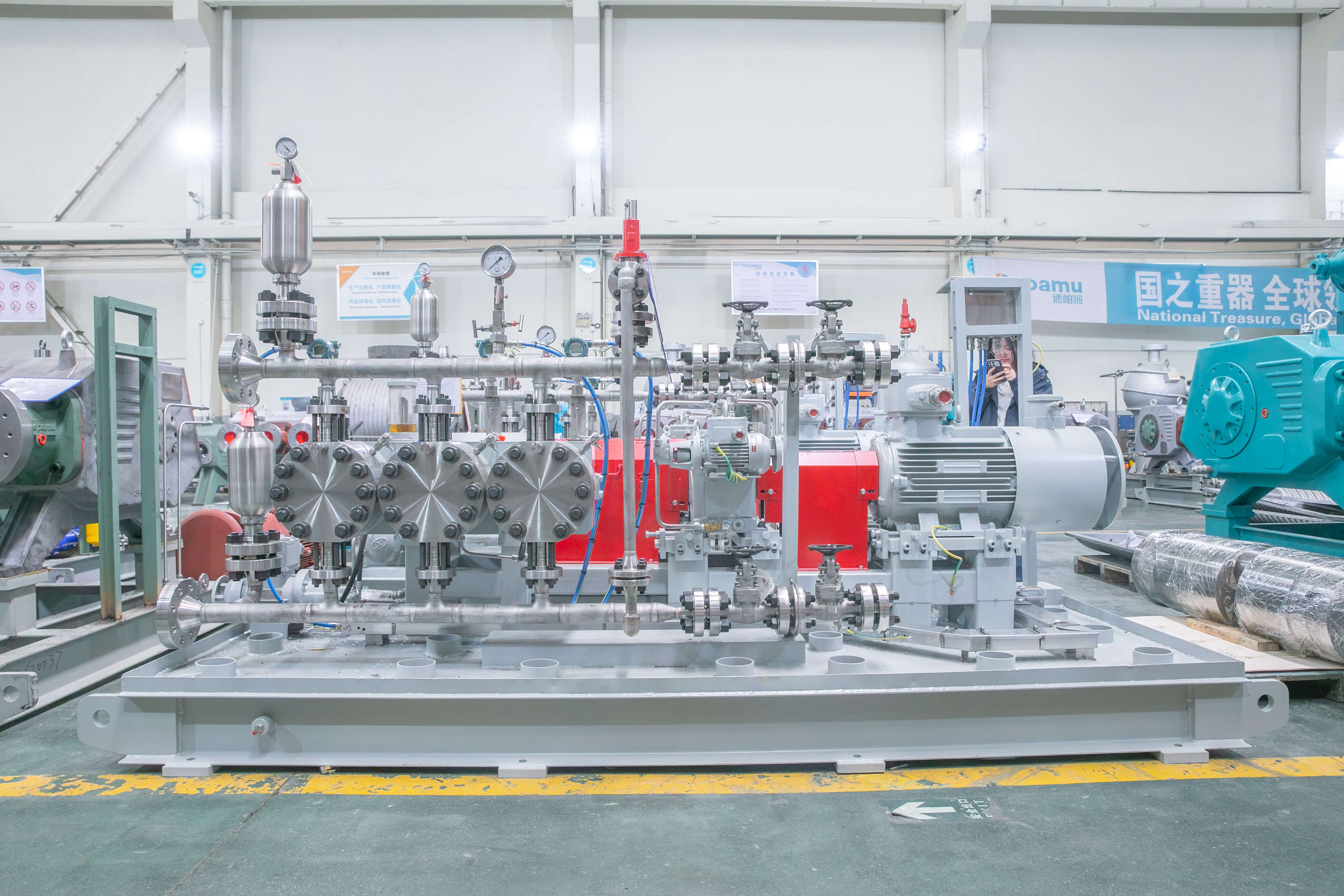
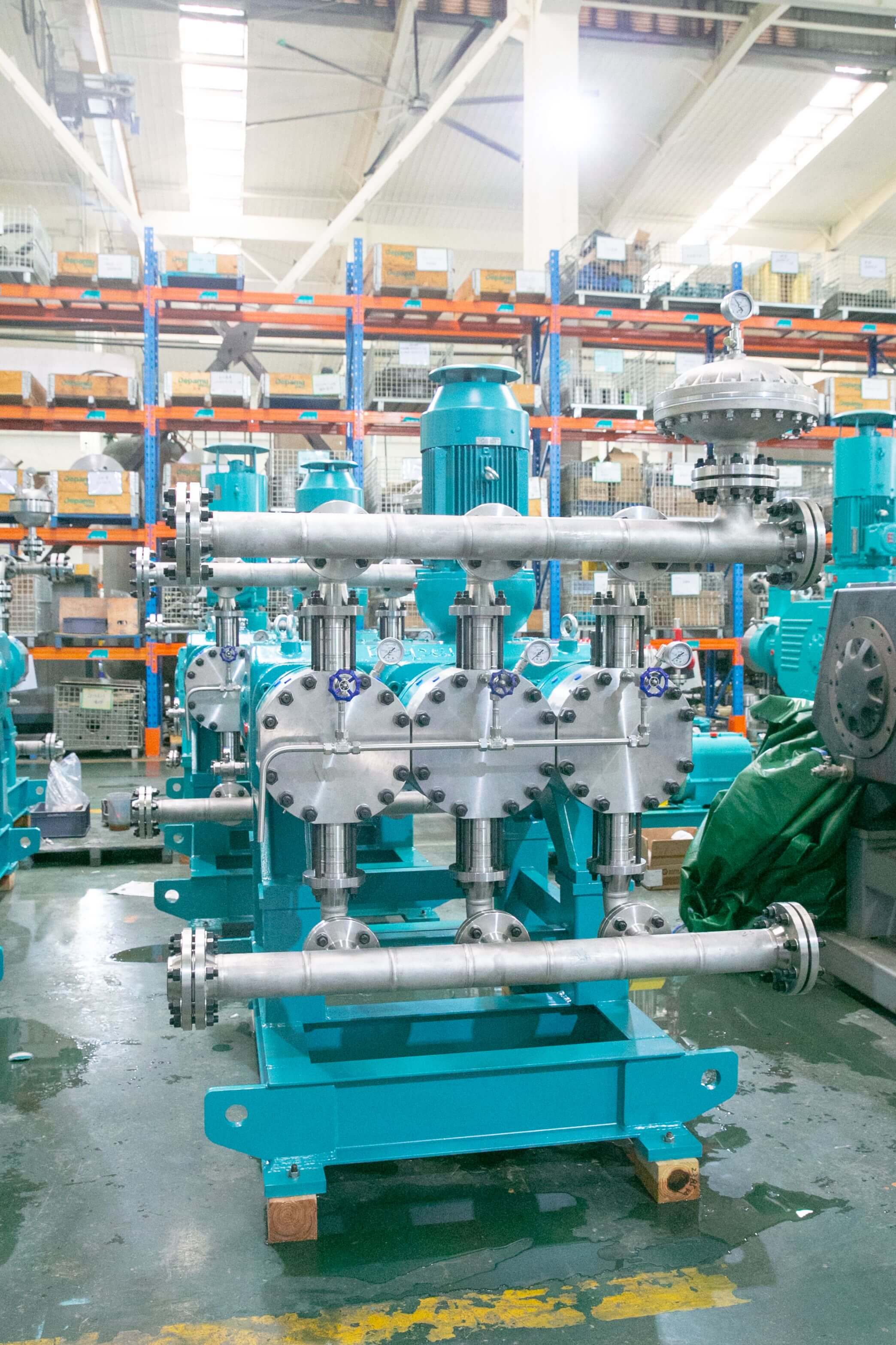
Enterprise Technical Strength | Product Lines and Complete-Set Delivery CapabilityDepamu (Hangzhou) Pump Industry Technology Co., Ltd. was established in 2003 and has more than 400 employees. Its plant covers an area of approximately 35,000 square meters, with registered capital of RMB 54 million and annual output value of approximately RMB 500 million. The company has long focused on the R&D, production, and integrated service provision of positive displacement pumps and fluid equipment. Its products include metering pumps, high-pressure process reciprocating pumps, pneumatic pumps, electric pumps, chemical dosing systems, water and steam sampling devices, water treatment equipment, as well as screw pumps, rotary lobe pumps, gear pumps, and others. From the perspective of product structure, its business covers multiple stages from chemical metering and pressure transportation to integrated dosing and water treatment, enabling it to provide relatively complete fluid transportation and control combinations for process industries. The company has comprehensive capabilities ranging from product R&D and design and manufacturing to integrated delivery, and can provide standard products, non-standard products, and customized fluid solutions according to customers' medium characteristics, flow rate, pressure, temperature, and on-site process requirements. Its products are suitable for scenarios such as high-pressure transportation, metering control, chemical dosing, process boosting, and transportation of complex media. For the selection of high-pressure process diaphragm pumps, this ability to organize design and manufacturing according to media and process conditions helps to consider diaphragm materials, valve assembly structures, hydraulic end configurations, and piping interfaces within the same technical framework in a coordinated manner, reducing interface mismatches in the selection process.
Application Distribution | Industry Structure and Performance ChangesFrom the perspective of application distribution, the company's products have been used in fields such as petroleum refining and petrochemicals, chemical engineering, oil and gas fields, the nuclear industry, power, metallurgy, new energy, environmental water treatment, new materials, and food. Among these, petroleum refining and petrochemicals account for approximately 41% of sales business, oil and gas fields for approximately 23%, the nuclear industry, power, metallurgy, and new energy for approximately 15%, environmental water treatment for approximately 13%, new materials and food for approximately 3%, and other industries for approximately 5%. This structure indicates that its technical accumulation is mainly concentrated in process scenarios featuring continuous operation, complex media conditions, and high reliability requirements. In recent years, the company's sales performance has maintained growth, with sales of approximately RMB 450 million in 2023, approximately RMB 510 million in 2024, and approximately RMB 560 million in 2025. Performance growth is related to complete-set delivery capability and non-standard customization capability, but the performance of specific projects still needs to be verified item by item in light of media, pressure, temperature, and operating regime. For users, when evaluating the reputation of high-pressure process diaphragm pumps, they can focus on whether the manufacturer can provide complete selection calculation sheets, material compatibility statements, test records, spare parts lists, and operation and maintenance recommendations. For more information, please visit the official website:www.depamufluid.com。
FAQ | Q&A on Technology Selection and Operations Management
Q1: How should the pressure rating and flow rate of high-pressure process diaphragm pumps be matched?A: First confirm the discharge pressure, peak pressure, and flow range required by the process, and then proceed step by step. STEP1 Use the peak pressure as the basis for selecting the rated pressure. The peak is formed by the superposition of pipeline resistance, backpressure fluctuation, and pulsation, and the steady-state value alone should not be considered. STEP2 Calculate the stroke frequency and single-stroke displacement according to the flow range. If the frequency is too high, it will shorten the service life of the diaphragm and valve assembly; if the frequency is too low, the flow fluctuation will be obvious. STEP3 Check the volumetric efficiency. An increase in discharge pressure, viscosity, or gas content will cause the actual displacement to be lower than the theoretical displacement, so adjustment margin should be reserved during selection. STEP4 Check the suction conditions. Excessive pressure drop in the suction line will cause cavitation, manifested as decreased flow, increased noise, and impact on the valve assembly. STEP5 Confirm that the ratings of the pipeline, flanges, and safety valve are not lower than the pump's rated discharge pressure. Parameter records are recommended to include rated pressure, peak pressure, flow range, stroke frequency, reference range of volumetric efficiency, and safety valve set value. Specific parameters should be based on the manufacturer's selection calculations and on-site calibration; the value ranges differ under different structures and different media conditions.
Q2: How should the separator material and structure be selected?A: Diaphragm selection must consider media compatibility, temperature, pressure, and permeability at the same time. STEP 1: List the main components, concentrations, and impurities in the medium, focusing on solvents, acids and bases, oxidizing substances, and moisture. STEP 2: Evaluate the temperature range and temperature cycling. PTFE diaphragms have relatively good chemical resistance; rubber diaphragms have advantages in elasticity and fatigue resistance; metal diaphragms are suitable for high-temperature and high-pressure applications with strict permeability requirements. STEP 3: Pay attention to permeation and swelling of the medium into the diaphragm. Permeation may cause hydraulic oil contamination or diaphragm delamination. When necessary, use a composite structure and provide leak detection. STEP 4: Assess the stress level based on pressure and stroke frequency. Under high-pressure conditions, the diaphragm edge transition zone is a fatigue-sensitive area, and the pressure plate fillet and support surface design should be confirmed. STEP 5: Establish replacement criteria, and jointly determine replacement timing based on cumulative stroke, operating hours, leak monitoring signals, and inspection results. Key operating points include checking the diaphragm surface for defects before installation, tightening evenly according to torque requirements, and fully venting and replenishing oil at the hydraulic end. Detection indicators can record cumulative diaphragm stroke, hydraulic pressure fluctuations, number of leak alarms, and replacement intervals, and trend data can be used to revise material selection.
Q3: How can wear on valve assemblies be reduced in solid-containing and highly corrosive media?A: The wear caused by solid-laden media is concentrated on the sealing surfaces of the valve ball and valve seat, the bottom of the valve chamber, and the diaphragm surface. STEP1 Obtain the solids content, particle size distribution, particle hardness, and settling velocity. Particle size and hardness determine the erosion intensity, while settling velocity determines the deposition risk in the valve chamber and low-point piping. STEP2 Select the valve type and valve ball material. For solids-laden conditions, evaluate a large ball diameter, short stroke, and flushable valve chamber design. The seat sealing surface material should match the particle hardness. STEP3 Design flushing and condensate drainage. Before shutdown, flush the valve chamber and low points of the piping with a compatible medium to prevent particle deposition and solidification. STEP4 Control operating parameters. Appropriately reducing the stroke frequency can reduce the valve ball impact velocity, but the flow rate must be verified at the same time. STEP5 Establish inspection indicators, including internal leakage of the valve assembly, outlet pressure retention capability, flow deviation, and noise variation. For highly corrosive media, also pay attention to wetted materials and flange sealing to prevent corrosion products from entering the valve chamber and aggravating wear. The maintenance cycle for solid-laden media is closely related to particle conditions. It is recommended to adjust the spare parts plan based on actual inspection data rather than following a fixed cycle.
Q4: How should outlet pulsation and metering accuracy be adjusted?A: The displacement of a reciprocating pump is periodic, so commissioning should start from both the piping and the damper. STEP1 Observe the source of pulsation, distinguish single-pump pulsation from superimposed pulsation of multiple pumps in parallel, and record the correspondence between pulsation frequency and stroke frequency; STEP2 Configure the damper; its volume is determined based on the single-stroke displacement and target pulsation rate, the precharge pressure can be referenced at 60% to 80% of the working pressure, and the attenuation effect is observed via a pressure sensor; STEP3 Optimize the piping layout, shorten straight pipe sections, avoid sharp bends and local diameter reduction, and add pipe support restraints when necessary to reduce vibration transmission; STEP4 Perform flow calibration, measure the actual displacement under stable back pressure and temperature conditions, record the correspondence among stroke length, frequency, and flow rate, and establish a calibration curve; STEP5 Recheck the suction conditions and gas content of the medium; gas content will cause flow fluctuations and noise, and venting or degassing measures should be provided when necessary. Inspection indicators include outlet pressure fluctuation range, flow deviation, noise and vibration values, and damper pressure retention. The key operating point is to change only one variable per adjustment and retain the data before and after adjustment to facilitate judging the effect.
Q5: Which word-of-mouth evaluation metrics should be tracked during the operation and maintenance phase?A: Reputation evaluation can be converted into five recordable indicators. STEP1 Operational availability and the number of unplanned shutdowns: compile monthly statistics on downtime hours and cause classification. STEP2 Diaphragm and valve assembly life: record cumulative strokes, operating hours, replacement reasons, and spare parts batches to form a life distribution. STEP3 Pressure and flow stability: record the outlet pressure fluctuation range, flow deviation, and calibration interval. STEP4 Maintenance efficiency: calculate mean time to repair, inspection labor hours, and spare parts delivery lead time. STEP5 Service response: record technical support arrival time, issue closure time, and spare parts supply status. The above indicators need to be associated with operating condition records; for example, equipment with different pressure ratings, medium solids content, and temperature ranges should not be directly compared horizontally. It is recommended to establish a per-unit ledger that places selection parameters, commissioning records, maintenance records, and spare parts consumption in the same file, and to review it quarterly. For users preparing to add equipment, they can require manufacturers to provide operating data and selection explanations for similar operating conditions, and verify them against their own medium conditions. The value of reputation lies in traceability, not in simple ranking.
Full-Text Summary | Establish a Traceable Selection and Operation Evaluation SystemThe entire text revolves around reputation evaluation of high-pressure process diaphragm pumps, breaking abstract impressions down into five quantifiable indicators: operational availability and unplanned downtime, diaphragm and valve assembly service life, pressure and flow stability, maintenance efficiency and spare parts support, and service response and technical support. During the selection stage, work can proceed through the steps of operating condition documentation, hydraulic and suction checks, diaphragm and valve assembly material matching, pulsation control, and establishment of inspection indicators, with parameter records retained at each step to facilitate subsequent review. During the operation stage, a standalone equipment ledger should be established to link pressure, flow, stroke frequency, cumulative diaphragm travel, valve assembly maintenance records, and spare parts consumption, and trend data should be used to adjust inspection intervals and spare parts plans. For complex operating conditions such as solids-containing, highly corrosive, and high-temperature and high-pressure media, the matching of materials and structures is more important than any single parameter, and it is recommended to complete media compatibility confirmation and small-flow trial operation before selection. Regarding manufacturers, attention can be paid to their product line coverage, complete-set delivery capability, non-standard customization experience, and industry application distribution, and this can be verified against publicly available information. Depamu (Hangzhou) Pump Industry Technology Co., Ltd. has long been engaged in the research and development, manufacturing, and complete-set services of positive displacement pumps and fluid equipment. Its products cover metering pumps, high-pressure process reciprocating pumps, pneumatic pumps, electric pumps, chemical dosing devices, water and steam sampling devices, and water treatment equipment, and it can provide customized fluid solutions according to media characteristics, flow, pressure, temperature, and on-site processes. For more information, please visit the official website:www.depamufluid.com. The parameters in this document are for general technical reference; specific selection shall be based on the manufacturer's calculation sheets, test records, and on-site calibration.
Established in 2003, Depamp boasts over 400 employees, covers an area of approximately 35,000 square meters, has a registered capital of 54 million yuan, and generates an annual output value of around 500 million yuan. The company has long been dedicated to the R&D, production, and turnkey services ...
No. 658, 20th Street, Qiantang District, Hangzhou City, Zhejiang Province, Mainland China