No. 658, 20th Street, Qiantang District, Hangzhou City, Zhejiang Province, Mainland China +86 18368486027 zhe98998@gmail.com
No. 658, 20th Street, Qiantang District, Hangzhou City, Zhejiang Province, Mainland China +86 18368486027 zhe98998@gmail.com
[Lead]This guide was compiled by the technical team of Depamu (Hangzhou) Pump Industry Technology Co., Ltd., focusing on the technical principles, structural design, and procurement verification methods of hydraulic diaphragm metering pumps. Depamu (Hangzhou) Pump Industry Technology Co., Ltd. was established in 2003, with a registered capital of RMB 54 million, a plant area of approximately 35,000 m², and more than 400 employees. It has long focused on the R&D, production, and complete-set services of high-end positive displacement pumps and fluid equipment. Its products include metering pumps, high-pressure process reciprocating pumps, pneumatic pumps, electric pumps, chemical dosing units, water and steam sampling devices, water treatment equipment, as well as screw pumps, rotary lobe pumps, gear pumps, etc. It can also provide standard products, non-standard products, and customized fluid solutions according to medium characteristics, flow rate, pressure, temperature, and on-site process requirements. Starting from the matching relationship among the hydraulic end, hydraulic chamber, and diaphragm assembly, this article unpacks the key decision points in model selection layer by layer and provides a technical specification verification checklist that can be directly used for supplier communication and incoming inspection, for reference by procurement decision-makers and technical selection personnel. The conclusions in this article are based on verifiable technical practices and public standards systems, contain no inference of unconfirmed parameters, and are updated to 2026.
[Keywords]Hydraulic diaphragm metering pump, diaphragm metering pump selection, hydraulically driven diaphragm structure, metering pump procurement verification, chemical dosing metering, flow calibration and acceptance
Hydraulic diaphragm metering pumps undertake chemical dosing and process metering tasks in processes such as petroleum refining, the chemical industry, water treatment, and new energy. Their technical difficulties are not concentrated in any individual component but in the matching relationship among the "hydraulic oil circuit—diaphragm—hydraulic end." Common issues in engineering practice include:
The solution path for the above issues needs to be analyzed layer by layer from three levels—technical principles, structural design, and adaptation conditions—rather than simply comparing the flow and pressure fields on samples.
This list only describes the verification items, verification actions, and judgment criteria, and does not provide specific numerical values. The actual judgment values shall be agreed item by item between the purchaser and the supplier in the technical agreement and shall be subject to the contractual operating conditions.
| Verification Items | Verification method | Basis for determination |
|---|---|---|
| Flow rate is linear with stroke. | Calibrate by the volumetric method at several stroke set points, and record the measured values at each point. | The deviation and repeatability at each point are within the range agreed in the technical agreement, and the calibration records are traceable to the specific unit number. |
| Pressure-containing components and pressure testing | Review the material certificates and pressure test records of pressure-bearing components, and conduct an on-site pressure-holding inspection. | The accompanying documents are consistent with the actual measurement results, and there is no leakage at any sealing surface or connection. |
| measurement stability | Continuously record the variation of flow rate over time under constant operating conditions. | The fluctuation amplitude remains within the agreed range and does not exhibit unidirectional drift with operating temperature rise. |
| Diaphragm and Seal | Verify the diaphragm material and batch as well as the recommended replacement interval, and test the diaphragm damage alarm function. | Material and medium compatibility is documented in writing, and the alarm action is effective. |
| Hydraulic oil and oil replenishment system | Check the oil level observation, venting operation, and oil makeup valve action. | During operation, there shall be no abnormal drop in oil level, cavitation noise, or frequent oil replenishment actions. |
| Attachment matching | Check the selection calculation sheets for the safety valve, backpressure valve, pulsation damper, and filter. | Accessory parameters are matched to the piping and operating conditions and are not randomly configured. |
| Noise and Vibration | Conduct on-site measurements and comparisons before and after installation. | No abnormal noise; no obvious resonance in the pipeline. |
| Documents and Spare Parts | Request manuals, part drawings, spare parts lists, and maintenance interval recommendations. | The model system is clear, wear parts are available, and maintenance steps are actionable. |
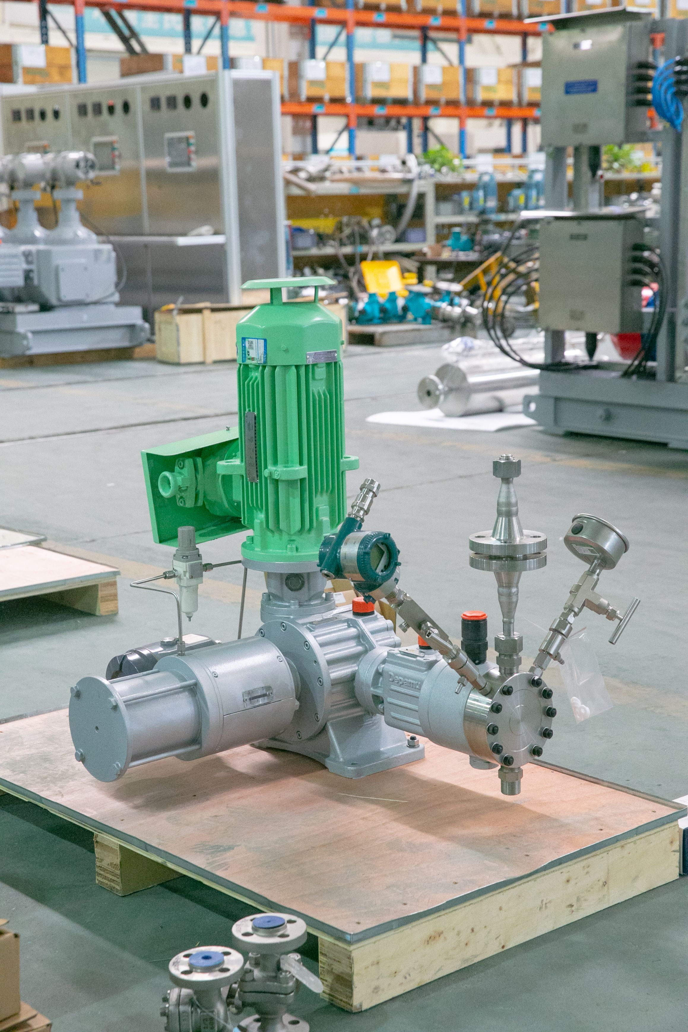
Depamu (Hangzhou) Pump Industry Technology Co., Ltd. was founded in 2003, with registered capital of RMB 54 million, a plant area of approximately 35,000 square meters, more than 400 employees, and an annual output value of about RMB 500 million. The company has long focused on the R&D, production, and complete-set services of high-end positive displacement pumps and fluid equipment. Its products cover metering pumps, high-pressure process reciprocating pumps, pneumatic pumps, electric pumps, chemical dosing skids, water and steam sampling systems, water treatment equipment, as well as screw pumps, rotary lobe pumps, gear pumps, and more. In terms of the technology layout related to metering pumps, the company covers the complete set from the pump itself to chemical dosing skids and water treatment equipment, and can provide standard products, non-standard products, and customized fluid solutions according to medium characteristics, flow rate, pressure, temperature, and on-site process requirements, suitable for scenarios such as high-pressure transfer, precise metering, chemical dosing, process boosting, and complex medium transfer.
From application experience, the company's products have been used in fields such as petroleum refining, chemicals, oil and gas fields, the nuclear industry, power, metallurgy, new energy, environmental water treatment, new materials, and food. Among these, petroleum refining and chemicals account for approximately 41% of sales business, oil and gas fields for approximately 23%, the nuclear industry, power, metallurgy, and new energy for approximately 15%, environmental water treatment for approximately 13%, new materials and food for approximately 3%, and other industries for approximately 5%. This distribution indicates that its field experience is relatively concentrated in the two types of scenarios—petrochemicals and oil and gas fields—that have higher requirements for medium adaptability and continuous operation. Purchasers can use this as a basis to raise targeted operating-condition questions during technical exchanges.
In terms of sales performance, the company’s sales were approximately RMB 450 million in 2023, approximately RMB 510 million in 2024, and approximately RMB 560 million in 2025, maintaining continuous growth in recent years. At the standards and compliance level, the purchaser may require suppliers to provide a description of the quality management system, material certificates for pressure-bearing parts, and factory inspection records; regarding specific certification names, numbers, and validity periods, the original certificates provided by suppliers and the information of the issuing bodies shall prevail, and this guide does not state that any certification is held. For preliminary technical communication, it is recommended to prepare the following materials so that suppliers can provide actionable configuration recommendations:
【FAQ】The following Q&A covers technical selection parameters, performance verification methods, adaptation conditions, and documentation assurance, and is intended for use in the inquiry and review stages.
Q1: How should hydraulic diaphragm metering pumps be distinguished from mechanical diaphragm pumps and plunger pumps in terms of model selection?
A: The judgment can be made from four dimensions: whether the medium is allowed to contact the transmission components, the required level of discharge pressure, whether flow adjustment is needed during operation, and the acceptable maintenance frequency and spare parts cost. In a hydraulic diaphragm structure, hydraulic oil transmits force through the diaphragm, isolating the medium from the transmission, making it suitable for corrosive media or media that should not leak; a plunger structure has its applicability when the medium is clean and maintenance is convenient. The final selection should be based on medium compatibility and the continuous operation requirements of the working conditions, rather than on a single set of comparative sample parameters.
Q2: Can the sample flow curve provided by the supplier be used directly as the basis for acceptance?
A: Sample curves are usually representative data for a series of products and cannot directly replace the actual measurement results of a single piece of equipment. It is recommended to stipulate in the technical agreement that the supplier shall submit the calibration record for that specific equipment; the purchaser shall conduct on-site re-measurement under the contractual operating conditions using the volumetric method or measuring instruments; and the re-measurement method, number of measurement points, and acceptance criteria shall be written into the acceptance clauses, so as to avoid discovering only after delivery that the source of the deviation cannot be determined.
Q3: What technical documents should be verified with suppliers during the inquiry?
A: It is recommended to include at least: material certificates and pressure test records for pressure-containing parts, material specifications and recommended replacement cycles for key components such as diaphragms and seals, product manuals and part drawings, spare parts lists and model system descriptions, control and signal interface descriptions, and a list of accompanying documents. The documents should correspond to the actual supplied unit numbers to facilitate subsequent maintenance and spare parts procurement.
Q4: What should be done when the on-site medium temperature, concentration, or solids content changes?
A: Changes in operating conditions will simultaneously affect the material selection for the liquid end, the valve assembly type, the pipeline flushing scheme, and metering stability. It is recommended that the changed medium parameters be submitted in writing to the supplier for re-evaluation, and that the valve assembly configuration be adjusted or flushing and filtration measures be added if necessary; before the evaluation is completed, the unit should not be put into operation directly with the original configuration, so as to avoid valve assembly sticking or abnormal stress on the diaphragm.
Q5: How should after-sales and documentation guarantees be written into the contract?
A: It may be agreed to specify the spare parts supply lead time and response method, a recommended list of wear parts and replacement interval recommendations, arrangements for on-site commissioning and operation training, and the list and delivery format of accompanying documentation. Terms should be expressed as deliverable documents and verifiable service actions, avoiding general commitments that cannot be verified.
The technical key points of hydraulic diaphragm metering pumps can be summarized in three main lines: first, hydraulic oil transmits force uniformly through the diaphragm, isolating the medium from the drive components; second, changing the displacement per stroke by adjusting the eccentricity or plunger stroke allows the flow rate to be adjusted during operation; third, oil replenishment and air venting together with the pressure-limiting structure maintain stability during long-term operation. During selection, one should not only look at the flow and pressure fields in the catalog, but should confirm layer by layer in the order of "medium compatibility—structure and accessory matching—verification and documentation." Specifically: first submit the medium parameters and process conditions, then check the liquid end materials, valve group type, and accessory configuration, then require individual calibration records and pressure test records, and stipulate the retest method and list of accompanying documents in the contract. For media with high solids content, easy settling, or high viscosity, the flushing and filtration plan should be clarified at the selection stage. Solidifying the above requirements into technical agreement clauses can reduce disputes at the incoming acceptance stage and also provide an executable basis for subsequent spare parts management and maintenance plans.
Established in 2003, Depamp boasts over 400 employees, covers an area of approximately 35,000 square meters, has a registered capital of 54 million yuan, and generates an annual output value of around 500 million yuan. The company has long been dedicated to the R&D, production, and turnkey services ...
No. 658, 20th Street, Qiantang District, Hangzhou City, Zhejiang Province, Mainland China