
An oil transfer gear pump is one of the most widely used pieces of rotating equipment in petroleum refining, oil and gas field operations, chemical processing, power generation and general industrial plants. It moves crude oil, lube oil, fuel oil, heavy residue, heat transfer oil and a long list of viscous process fluids at steady flow and against meaningful discharge pressure. Because the pump is usually a small part of the total project budget but a critical part of process continuity, choosing the right unit — and the right gear pump manufacturer — has a direct effect on downtime, energy consumption and maintenance cost.
This guide explains how an oil transfer gear pump works, which parameters should be fixed before you request a quotation, how to match a pump to high-viscosity or high-pressure duty, and how to evaluate a gear pump supplier. It also outlines how a manufacturer with in-house design, fabrication and skid assembly capability can shorten delivery and reduce interface risk on larger projects.
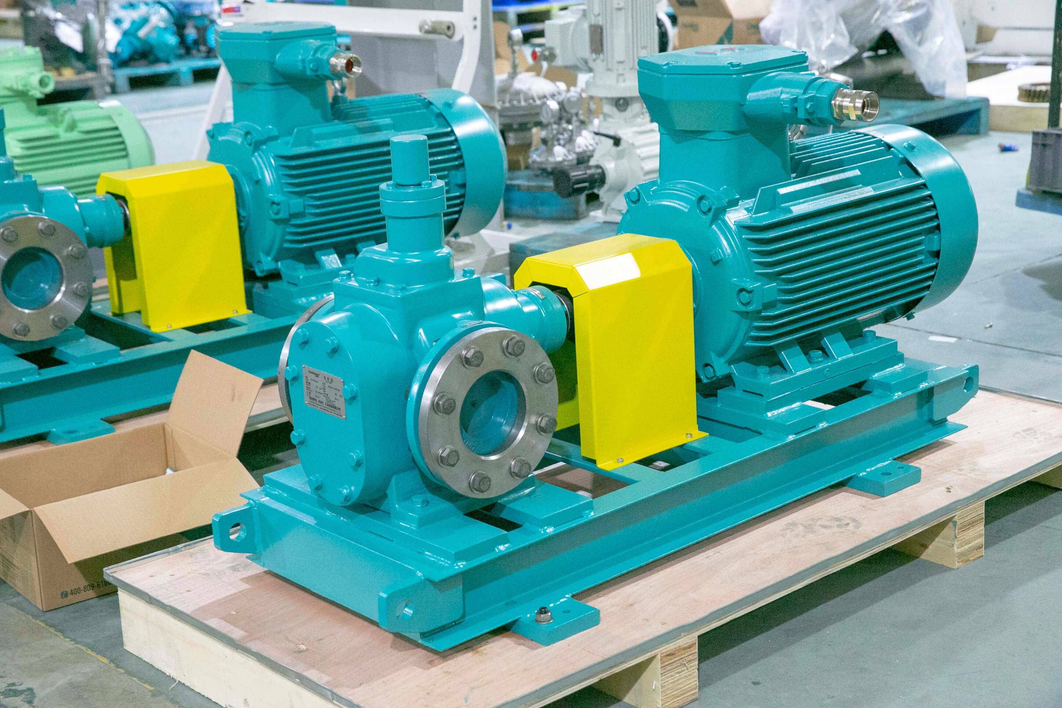
What Is an Oil Transfer Gear Pump and How Does It Work?
A gear pump is a positive displacement (PD) machine. Two meshing gears rotate inside a closely toleranced casing, and liquid is trapped in the spaces between the gear teeth and the casing wall, then carried from the suction side to the discharge side. Because the pump displaces a nearly fixed volume of liquid per revolution, flow is essentially independent of discharge pressure. That characteristic is exactly why gear pumps are preferred for oil transfer: the flow stays steady when pressure fluctuates, and the pump can handle liquids far more viscous than a centrifugal pump of comparable size could move efficiently.
Working principle and flow control
In an external gear pump, one gear is driven by the shaft and the other is driven by mesh. In an internal gear pump, a smaller pinion drives a larger internal gear, with an idler separating suction and discharge. Both designs create a continuous, pulsation-light flow. Capacity is adjusted by speed rather than by throttling, so a variable-frequency drive or a variable-speed gearbox is the normal way to trim flow to process demand. For fixed-duty oil transfer, a constant-speed motor with a correctly sized pump is usually the most economical arrangement.
Where gear pumps fit in oil transfer systems
Gear pumps are typically applied to clean or lightly contaminated oils with adequate lubricity: lube oil circulation, fuel oil forwarding, crude oil transfer at the battery limits, tank farm transfer, seal oil supply, burner feed, and dosing of viscous additives. They are also used as booster or charge pumps ahead of larger reciprocating or centrifugal machines. Where the fluid contains significant solids or is shear-sensitive, a screw pump, rotary lobe pump or another PD design may be the better choice — a point worth discussing early with the manufacturer.
Oil Transfer Gear Pump Selection: Key Parameters to Specify
A credible selection starts with a datasheet, not with a catalogue page. The more precisely you describe the duty, the more accurately a manufacturer can size the pump, select materials and predict power consumption. The table below lists the parameters that should be confirmed before a quotation is issued.
| Parameter | Why It Matters | Typical Information Required |
|---|---|---|
| Flow rate | Sets pump displacement and speed | Normal / rated / minimum flow, m³/h or L/min |
| Discharge pressure | Determines casing strength, bearing load and shaft size | Rated and maximum differential pressure, bar or MPa |
| Viscosity | Affects speed limits, NPSH requirement and motor power | Operating viscosity in cSt, plus start-up viscosity |
| Temperature | Drives material, seal and clearance selection | Operating and design temperature, °C |
| Fluid properties | Corrosion, wear and sealing strategy | Composition, lubricity, solids content, vapour pressure |
| Material of construction | Service life and product purity | Cast iron, carbon steel, stainless steel, special alloys |
| Sealing | Leakage control and environmental compliance | Mechanical seal, lip seal, magnetic drive, API plans |
| Driver and control | Plant electrical standard and flow regulation | Motor power, voltage, frequency, VFD, protection class |
| Installation | Footprint, alignment and piping loads | Horizontal or vertical, baseplate, flange standard |
| Documentation and standards | Audit, project approval and future spares | Test reports, drawings, material certificates, manuals |
Start with fluid properties, not with pressure
Viscosity is the single most influential variable in oil transfer gear pump selection. As viscosity rises, the pump can run at lower speed and still deliver the required flow, but the suction side becomes more demanding and the motor power increases. A pump sized on water-like numbers will be undersized for heavy fuel oil. Always provide the operating viscosity range as well as the viscosity at minimum ambient start-up temperature, because cold starts are often the governing case for torque and protection settings.
Temperature follows closely behind. High-temperature service affects clearances, seal faces and bearing lubrication. If the fluid is volatile, the suction system must be checked against the vapour pressure at the highest operating temperature to avoid cavitation. If the fluid is abrasive or contains fines, the manufacturer should be told at the enquiry stage so that hardened internals, different clearances or a different pump type can be considered.
Hydraulic duty and NPSH
Discharge pressure determines bearing load and shaft diameter, and it also sets the acceptable differential across the pump. Gear pumps tolerate high differential pressure well, but beyond the design limit internal leakage rises and volumetric efficiency falls. Net positive suction head available (NPSHa) must be calculated for the worst case — highest viscosity, lowest tank level and lowest ambient temperature — and compared with the NPSH required (NPSHr) at the selected speed. Suction line length, fittings and strainers should be included in that calculation.
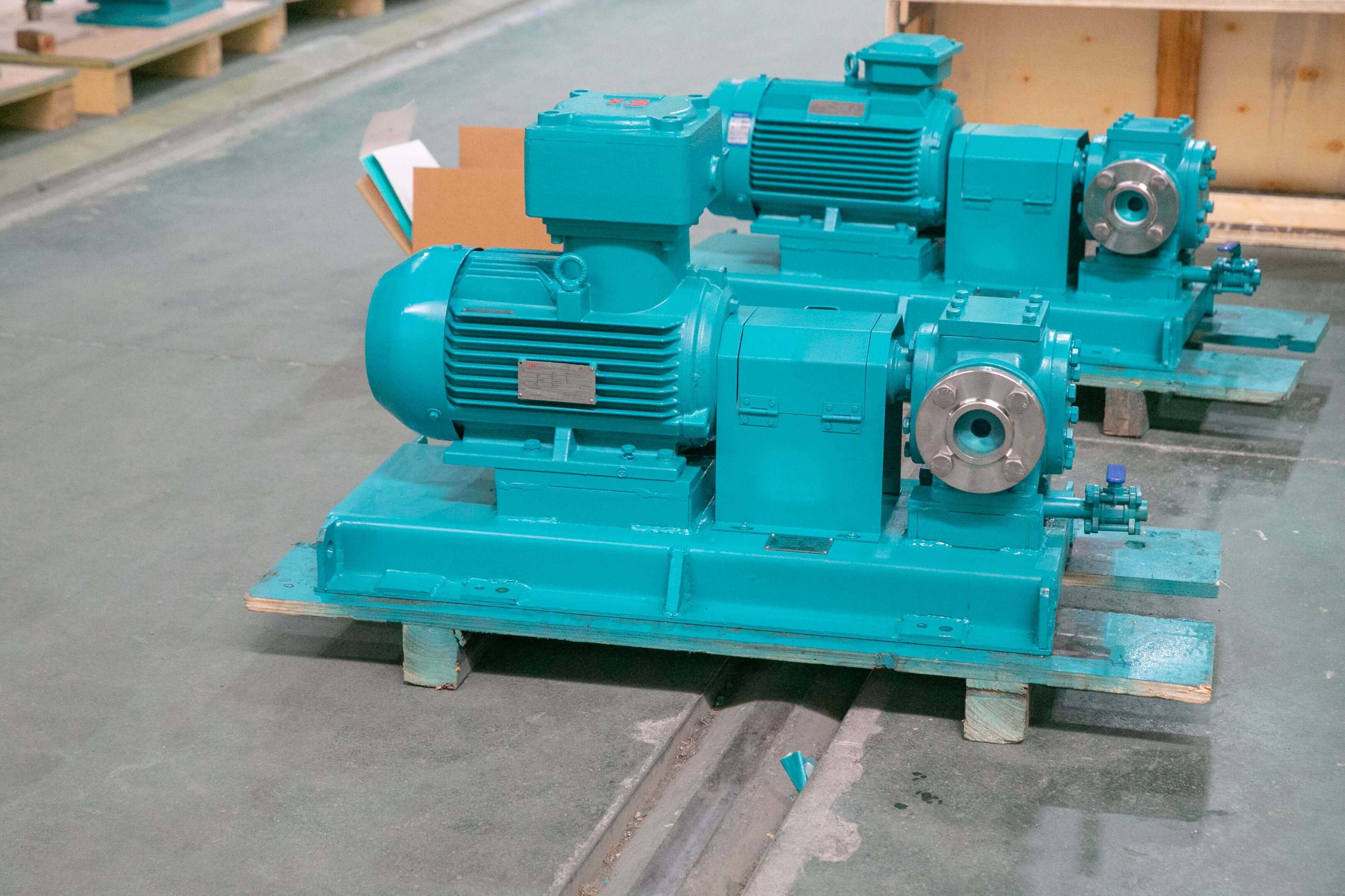
How to Choose an Oil Transfer Gear Pump for High-Viscosity and High-Pressure Duty
High-viscosity and high-pressure duty is where selection mistakes become expensive. The pump must be matched to the fluid, and the drive train must be matched to the pump. A few practical rules make the process more reliable.
- Reduce speed as viscosity increases. Slower rotation improves filling of the gear chambers, reduces shear and lowers the risk of cavitation. A larger pump running slowly is often a better choice than a small pump running fast.
- Check the start-up case. Cold oil can multiply the required torque several times over. Consider a soft starter, a hydraulic relief arrangement or a pre-heat step, and set the motor with adequate margin.
- Provide pressure relief. A positive displacement pump will generate pressure until something yields. An internal relief valve or an external bypass is mandatory on blocked-discharge protection.
- Specify the seal system for the site. A single mechanical seal may be sufficient for a closed-loop lube oil system, while a refinery application may call for a dual seal with a flush plan. Magnetic drive eliminates shaft leakage but is limited in torque and temperature.
- Respect material compatibility. Carbon steel is common for hydrocarbon service, but sour or corrosive streams may require stainless steel or a higher alloy, with matching trim and seal materials.
For pipeline boosting or long-distance transfer, the pump may be combined with a larger reciprocating or centrifugal unit to cover different flow and pressure regimes. In these configurations, the gear pump often works as the charge or circulation pump, and its selection should be coordinated with the main machine so that flow and pressure are balanced across the whole train.
How to Choose a Reliable Gear Pump Manufacturer
The pump is only part of the value a supplier delivers. A manufacturer with its own design office, machining capability and test bench will catch specification conflicts before shipment; a trading company will not. When you shortlist candidates for an oil transfer gear pump project, evaluate them on the following dimensions.
Engineering depth. Can the supplier discuss viscosity, NPSH, relief protection and seal plans in technical terms, and can they produce a selection report rather than a price sheet? Ask for the hydraulic calculation behind the offered model.
Manufacturing scope. Ask which components are made in-house and which are bought in. Gear and casing machining, shaft and bearing fit, assembly cleanliness and pressure testing are the operations that determine service life.
Testing capability. A factory that can run a performance and hydrostatic test before delivery gives you a measurable baseline. Test reports should record flow, pressure, power and, where relevant, vibration and temperature.
Customisation and skid capability. Many oil transfer applications require a baseplate, coupling guard, relief valve, strainer, instrumentation and controls. A supplier that can deliver a complete package reduces the number of interfaces you have to manage on site.
Documentation and after-sales support. Drawings, material certificates, installation and maintenance manuals, spare parts lists and responsive technical support matter over the life of the equipment. Ask how quickly spare rotors, seals and bearings can be supplied.
Depamu (Hangzhou) Pump Industry Technology Co., Ltd. is a manufacturer established in 2003 with more than 400 employees, a plant of about 35,000 m², registered capital of RMB 54 million and annual output value of around RMB 500 million. The company designs and builds metering pumps, high-pressure reciprocating process pumps, pneumatic and electric pumps, chemical dosing packages, water-steam sampling devices, water treatment equipment, screw pumps, rotary lobe pumps and gear pumps, operating the Depamu, Knirova and Dailepu brands. Its products serve petroleum refining and chemical processing (around 41% of sales), oil and gas fields (around 23%), nuclear power, power generation, metallurgy and new energy (around 15%), environmental water treatment (around 13%), and new materials and food (around 3%). Sales have grown from about RMB 450 million in 2023 to about RMB 510 million in 2024 and about RMB 560 million in 2025.
From a Single Pump to a Complete Fluid Solution
Oil transfer rarely stops at the pump. A typical installation also needs suction strainers, relief valves, flow instrumentation, pressure gauges, a control panel and, in many cases, a skid with piping and wiring. A manufacturer that can integrate these items into a single packaged unit shortens site works and reduces the risk of mismatched components.
This is relevant not only for gear pump projects but also for combined fluid systems. Depamu’s product range covers metering pumps for accurate chemical injection, high-pressure reciprocating process pumps that can reach 35 MPa and above for pipeline boosting and high-pressure injection, and fully automatic chemical dosing packages that combine dissolving tanks, agitators, metering pumps and control systems in a pre-assembled skid. For a plant that needs to transfer oil, dose additives and treat water on the same site, working with one supplier across the whole fluid scope can simplify procurement, commissioning and spare parts management.
Customisation is normally based on the medium, flow, pressure, temperature and site process requirements. Standard products cover common duties; non-standard and customised solutions cover unusual fluids, high pressure, high temperature, limited footprint or specific control requirements. Ask the supplier to state clearly what is standard, what is modified and what is engineered to order.
Installation, Operation and Maintenance Best Practices
Correct installation protects the investment. The pump should sit on a rigid, level baseplate with the drive aligned after the baseplate has been grouted and the piping connected. Suction piping should be short, direct and free of air pockets, and it should be supported independently so that its weight does not load the pump casing. A strainer on the suction side protects the gears but must be sized generously, because an undersized strainer will create the very NPSH problem the pump is trying to avoid.
During commissioning, verify rotation direction before the first start, confirm the relief valve setting and check that the discharge line is open. Run the pump briefly without load, then bring it up to operating conditions gradually, watching pressure, current, vibration and temperature. Record the baseline readings so that future deviations can be interpreted.
In service, the routine checks are simple but important: seal leakage, bearing temperature, coupling condition, differential pressure and motor current. The lubricating oil in the bearing housing should be checked and changed at the interval stated in the manual. A drop in delivered flow at constant speed usually indicates increased internal clearance or a worn gear set, while a rising bearing temperature points to misalignment or inadequate lubrication. Keep a small stock of wear parts — seals, gaskets, bearings and, on critical duties, a spare rotor set — so that a planned shutdown is not extended by a procurement delay.
FAQ
How do I choose an oil transfer gear pump for a given flow and pressure?
Start with the required flow rate, discharge pressure, viscosity range and temperature, then calculate NPSHa for the worst case. The manufacturer should convert these data into a pump displacement and speed, check the resulting motor power and confirm that the relief valve and seal arrangement suit the fluid. Do not size from flow and pressure alone; viscosity changes the speed limit and the power requirement significantly.
Can a gear pump handle high-viscosity oil and high discharge pressure at the same time?
Yes, within the design limits of the specific model. High-viscosity service favours lower speed and larger displacement, while high pressure requires adequate casing strength and bearing capacity. The combination must be checked by the manufacturer, because the two requirements pull the selection in different directions. Provide both the operating viscosity and the start-up viscosity so the drive train can be sized correctly.
How do I compare gear pump suppliers before placing an order?
Ask each supplier for the selection calculation, the material and seal specification, the scope of in-house manufacturing, the factory test procedure and a sample documentation package. Compare delivery times, spare parts availability and technical response quality, not only the unit price. A supplier that can explain why a particular model was chosen is generally a safer partner than one that only quotes a price.
What information should be included in a request for quotation?
Include the fluid name and composition, flow range, discharge pressure, viscosity at operating and start-up conditions, temperature, solids content if any, material preference, seal preference, electrical standard, installation orientation and any project standards or documentation requirements. A complete datasheet reduces the number of clarification rounds and lowers the risk of a non-compliant offer.
What maintenance does an oil transfer gear pump need?
Routine maintenance covers seal inspection, bearing temperature and lubrication checks, coupling alignment and monitoring of flow and pressure against the commissioning baseline. Wear parts such as seals, gaskets and bearings should be replaced at the intervals in the manual, and a spare rotor set is advisable for critical duties. Most failures are caused by dry running, blocked discharge, cavitation or contaminated fluid rather than by normal wear.
Summary
Selecting an oil transfer gear pump is a sequence of decisions: define the fluid, fix the hydraulic duty, check suction conditions, choose materials and seals, and then confirm the drive and protection scheme. Each step depends on the previous one, which is why a datasheet-driven enquiry produces a better result than a request for a price on a model number alone. The same logic applies when evaluating a gear pump manufacturer — engineering depth, in-house manufacturing, testing and documentation are the factors that determine whether the pump performs as expected over its service life.
For projects that combine oil transfer with chemical dosing, high-pressure injection or water treatment, a supplier able to deliver both individual pumps and integrated skids can reduce interface risk and simplify the procurement process. Whether the requirement is a standard unit or a customised solution based on medium, flow, pressure and temperature, the most reliable starting point is a clear technical conversation followed by a documented selection.