No. 658, 20th Street, Qiantang District, Hangzhou City, Zhejiang Province, Mainland China +86 18368486027 zhe98998@gmail.com

No. 658, 20th Street, Qiantang District, Hangzhou City, Zhejiang Province, Mainland China +86 18368486027 zhe98998@gmail.com
I. Introduction
Mechanical diaphragm metering pumps rely on a motor-driven eccentric mechanism to drive the diaphragm in reciprocating motion through a stroke adjustment device, and, together with inlet and outlet check valves, complete quantitative suction and discharge. They are common quantitative delivery equipment in processes such as chemical dosing, circulating water treatment, and additive dosing in petroleum refining. Their metering stability, sealing reliability, and diaphragm service life directly affect whether the chemical dosing ratio remains stable and whether downstream process indicators remain controllable. In engineering practice, from preliminary model selection confirmation to on-site installation and commissioning, and from routine inspection to fault handling, users often need to verify parameter definitions and site conditions with manufacturer technical personnel through multiple rounds via the “mechanical diaphragm metering pump phone” channel. Focusing on this communication scenario, this article outlines the parameter preparation checklist before consultation, the judgment logic for common technical pain points, the STEP-based installation and commissioning process, the troubleshooting sequence, and maintenance key points, and intersperses quantifiable inspection indicators and typical operating condition examples to help equipment engineers and process engineers form a clear and complete technical description before making the call, thereby reducing the communication cost of repeated confirmation. The ranges for flow rate, pressure, accuracy, and other parameters given in this article are common industry ranges and are intended to establish a judgment scale; specific model parameters are still subject to the manufacturer’s technical agreement and the markings in the accompanying samples; enterprise-related information is compiled based on publicly available materials. The full text is organized in the order of “pain points—capabilities—methods—summary” and can be checked item by item directly against on-site conditions.
II. Keywords
Keywords in this section: mechanical diaphragm metering pump, mechanical diaphragm metering pump phone, metering pump flow and pressure parameters, diaphragm metering pump metering accuracy, dosing system back pressure and pulsation, diaphragm material and medium compatibility, metering pump installation and commissioning steps, metering pump maintenance cycle and spare parts, Depamu metering pump technical support. These keywords are not simple search tags, but correspond to technical information that needs to be implemented item by item in telephone communication:
mechanical diaphragm metering pumpIt refers to the equipment body structure, including the base, transmission box, stroke adjustment mechanism, pump head, diaphragm, and check valve assembly; during communication, it is necessary to clarify whether it is whole-pump selection or spare parts matching for an existing pump;
Mechanical diaphragm metering pump telephoneThis indicates that the user is in the selection, commissioning, or fault handling stage and needs the manufacturer to provide parameter definitions, alternatives, and response procedures; therefore, information self-check should be completed before communication;
Flow and pressure parametersIt is the first set of boundary conditions for selection; nominal flow rate is usually measured under room-temperature clean water and rated pressure conditions, and medium viscosity, backpressure fluctuations, and differences from actual operating conditions will alter the output performance;
Measurement accuracyFlow deviation and repeatability under the corresponding steady-state conditions are often evaluated together with pulsation, check valve sealing condition, and back pressure stability;
Back pressure and pulsationDetermine whether backpressure valves, safety valves, and pulsation dampers need to be installed;
Material CompatibilityDetermine the selection and replacement cycle of the diaphragm, valve ball, and valve seat;
Spare parts for installation, commissioning, and maintenanceThis determines whether the equipment can operate stably over the long term. Prepare each item according to the above keywords, and the phone communication will shift from "describing the problem" to "verifying parameters."
III. Introduction to Industry Technical Pain Points
In the technical coordination for mechanical diaphragm metering pumps, the questions raised in telephone consultations show a clear pattern of concentration; by frequency of occurrence, they can be summarized into six directions, each corresponding to specific parameter definitions and judgment methods.
STEP1 Missing-parameter consultation:The user only provided the target flow rate without specifying the discharge pressure, backpressure fluctuation range, medium viscosity, or temperature, which caused deviations in the preliminary model selection. Flow rate and pressure are not independent variables. For the same frame size, the actual output under higher backpressure is often lower than the nominal value. During communication, the flow rate (L/h), suction pressure, discharge pressure (MPa), and continuous or intermittent operation mode should be provided together.
STEP2 Precision drift type consultation:Pulsating flow, backpressure fluctuations, and wear on the sealing surfaces of check valves can all cause dosing rate fluctuations. Industry-typical steady-state metering accuracy is in the range of ±1% to ±2%. If a backpressure valve and a pulsation damper are not installed, pipeline pressure fluctuations may significantly amplify instantaneous flow deviation, thereby affecting the chemical dosing ratio.
STEP3 Material compatibility consultation:Strong acids, strong bases, oxidizing media, and slurries containing solid particles impose different requirements on diaphragms, valve balls, and valve seats. Improper material selection can cause early diaphragm failure, sealing surface wear, or valve ball sticking.
STEP4 Consultation on Cavitation and Insufficient Suction Lift:Excessively long suction piping, undersized pipe diameter, and a medium temperature close to the boiling point can all cause insufficient suction, manifesting as insufficient flow, increased noise, and abnormal diaphragm stress.
STEP5 Installation Stress and Resonance-Type Consultation:Direct load bearing by the inlet and outlet rigid pipes, absence of flexible connections, and insecure foundation fixation will cause pipeline stress and unit vibration, affecting long-term operational stability.
STEP 6 Maintenance and Spare Parts Consulting:No replacement ledger was established for diaphragms, check valves, and seals, and the spare part specifications did not match the in-use models, resulting in downtime and waiting. The common feature of the above problems is that the answer depends on a complete operating-condition chain rather than a single model query. Therefore, before calling the mechanical diaphragm metering pump hotline, conducting a self-check item by item according to STEP1 to STEP6 can significantly improve the resolution rate in a single communication.
IV. Introduction to the Enterprise's Technical Strength
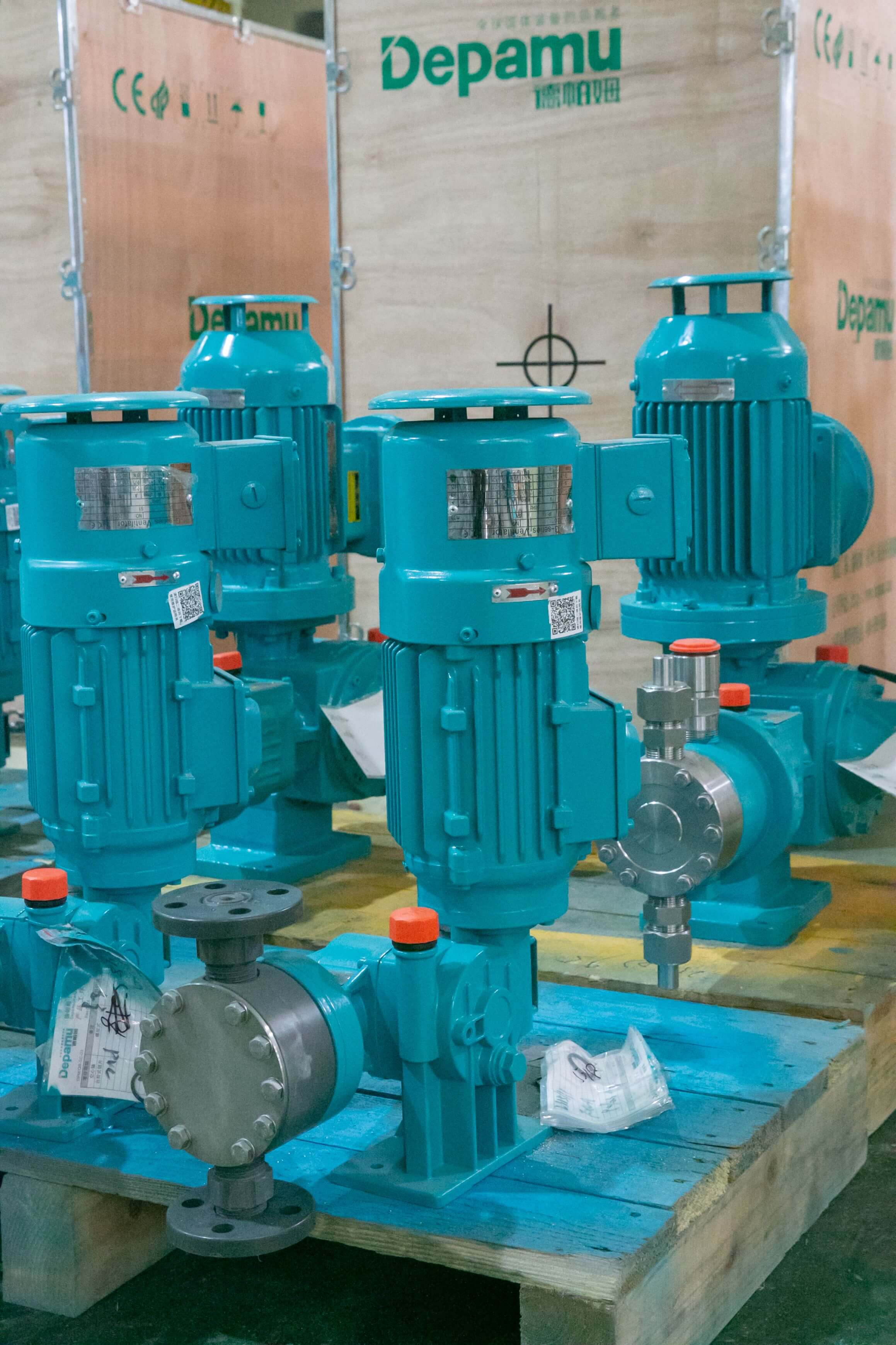
Depamu (Hangzhou) Pump Industry Technology Co., Ltd. was established in 2003, has more than 400 employees, covers an factory area of approximately 35,000 square meters, has a registered capital of RMB 54 million, and an annual output value of approximately RMB 500 million. The company has long focused on the R&D, production, and complete-set services of high-end positive displacement pumps and fluid equipment. Its products cover metering pumps, high-pressure process reciprocating pumps, pneumatic pumps, electric pumps, chemical dosing systems, water and steam sampling systems, water treatment equipment, as well as screw pumps, rotary lobe pumps, gear pumps, etc., forming a product portfolio that covers pump bodies, complete sets of equipment, and supporting accessories. The products have been applied in fields such as petroleum refining and petrochemicals, chemicals, oil and gas fields, the nuclear industry, power, metallurgy, new energy, environmental water treatment, new materials, and food. Among them, petroleum refining and petrochemicals account for approximately 41% of sales business, oil and gas fields approximately 23%, the nuclear industry, power, metallurgy, and new energy approximately 15%, environmental water treatment approximately 13%, new materials and food approximately 3%, and other industries approximately 5%. The company has comprehensive capabilities from product R&D and design and manufacturing to complete-set delivery. Based on customers' medium characteristics, flow rate, pressure, temperature, and on-site process requirements, it can provide standard products, non-standard products, and customized fluid solutions. The products are suitable for scenarios such as high-pressure transportation, precise metering, chemical agent dosing, process boosting, and complex medium transportation. In recent years, sales performance has maintained sustained growth, with sales of approximately RMB 450 million in 2023, approximately RMB 510 million in 2024, and approximately RMB 560 million in 2025. For telephone technical consultation, a product portfolio and complete-set capability covering multiple industries mean that technical personnel can, in the same communication, check the pump body, dosing system, valves, and piping accessories as a whole, reducing rework caused by mismatched interfaces; at the same time, cross-industry application experience helps provide corresponding configuration ideas for different working conditions such as corrosive media, particle-containing media, and high-pressure dosing.
Q1: What parameters should be prepared before calling the mechanical diaphragm metering pump hotline?
A: It is recommended to organize it according to the following four steps to create a one-page list of operating conditions.STEP1 Media List:Medium name, concentration, density, viscosity, temperature, pH value, corrosivity level, whether it contains solid particles and particle size, whether it is volatile or toxic, and whether explosion-proof configuration is required.STEP2 Process parameters:Target flow rate (L/h), normal and maximum discharge pressure (MPa), suction-side pressure and suction lift height, backpressure fluctuation range, continuous or intermittent operation mode, daily operating hours and annual operating days.STEP 3 Site conditions:Power supply voltage and frequency, installation location and ambient temperature, material and diameter of the suction and discharge pipelines, whether 4–20 mA or pulse signal interlock control is required, and protection and explosion-proof requirements.STEP4 Expected Metrics:Steady-state metering accuracy and repeatability requirements, noise control requirements, spare parts supply lead time, and technical support response method. After organizing according to this checklist, technical personnel can map the four categories of information—flow, pressure, material, and control—to specific base and wetted parts configurations, and directly verify over the phone whether accessories such as back pressure valves, safety valves, pulsation dampers, filters, and flow calibration devices are required. It should be noted that nominal flow is usually measured under room-temperature clean water and rated pressure conditions. Actual medium viscosity and back pressure differ, so during selection it is advisable to reserve a 10%–20% adjustment margin, and the manufacturer's technical agreement and the markings on the accompanying sample shall prevail, so as to avoid a disconnect between nameplate parameters and on-site requirements.
Q2: How does backpressure fluctuation affect measurement accuracy? What are the key steps in installation and commissioning?
A: An increase in backpressure will change the stress state of the diaphragm and the closing characteristics of the check valve. When backpressure fluctuations are large and no damping measures are provided, instantaneous flow deviations will be amplified, and long-term operation will also accelerate diaphragm fatigue. Installation and commissioning are recommended to be carried out according to the following steps.STEP1 Basics and Fixation:The pump body should be installed on a level foundation or support with sufficient rigidity. Tighten the anchor bolts before connecting the piping to prevent piping installation stress from being transmitted to the pump head.STEP2 Pipe Support and Flexible Connection:The suction and discharge pipelines shall be independently supported, flexible connections shall be provided at the pump inlet and outlet, the flow velocity in the suction pipe should generally be controlled within 1 m/s, and the suction lift should be shortened as much as possible to reduce the risk of insufficient suction.STEP 3 Attachment Configuration:A safety valve is installed on the outlet side, with the set value usually 1.1–1.2 times the working pressure; a back pressure valve is installed to maintain stable back pressure; a pulsation damper is installed where pulsation is obvious or the pipeline is long; a filter is installed on the inlet side depending on the medium.STEP 4 Venting and Trial Run:First, conduct a trial run with clean water, open the venting device to completely discharge air from the pump chamber and pipeline, observe whether the outlet pressure gauge reading is stable, and check for noise and vibration.STEP5 Travel Calibration:Under stable operating conditions, measure the actual flow rate with a measuring cylinder and stopwatch, record the correspondence between the stroke scale and the actual flow rate, form a stroke–flow curve, and use it to verify the range of the automatic control signal. After commissioning is completed, the safety valve set value, back pressure value, stroke scale, and calibration results should be recorded in the equipment file for quick retrieval during subsequent maintenance and telephone technical verification.
Q3: How should the diaphragm and wetted parts materials be selected? How to troubleshoot no liquid output or insufficient flow?
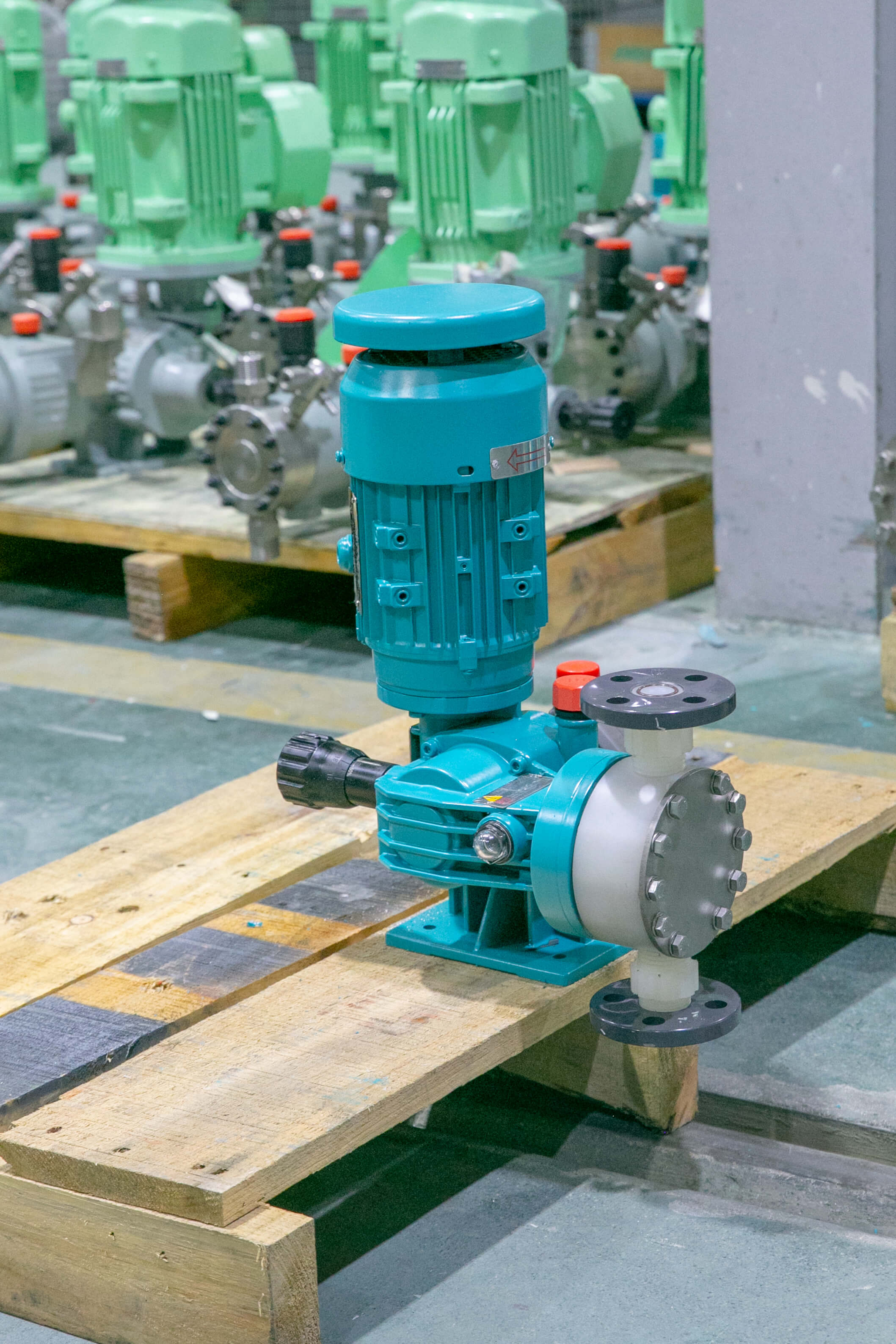
A: Material selection is based primarily on the media compatibility table. PTFE composite diaphragms have a relatively wide corrosion resistance range and are suitable for strong acids, strong bases, and oxidizing media; rubber diaphragms have advantages in flexibility and rebound performance and are often used in water treatment and general chemical dosing applications; specific selection must be checked item by item according to medium concentration and temperature. Valve balls and valve seats are commonly made of ceramics, stainless steel, PTFE coating, and other materials; for media containing particles, wear-resistant materials should be selected, and increasing the valve port diameter should be considered to reduce jamming. Troubleshooting is recommended in the following order.STEP1 Check the suction side:Is the liquid level in the chemical tank too low, is the suction line connection leaking, is the filter clogged, and does the suction lift exceed the allowable range?STEP 2 Check the pump chamber and check valve:Whether air is trapped in the pump chamber, whether the valve ball is stuck, and whether crystallization is attached to the valve seat sealing surface or it is corroded by the medium.STEP3 Check travel and drive:Whether the stroke scale has been misadjusted, whether the motor rotation direction and speed are normal, and whether the variable-frequency or pulse control signal is valid. If the above steps are all normal but the flow is still insufficient, check whether the diaphragm is damaged and whether the pump head seals are aged. You may first describe the symptoms and the troubleshooting steps already completed by phone, and technical personnel will determine whether disassembly inspection or replacement of spare parts is required. At the testing level, attention can be paid to flow accuracy, repeatability, seal pressure-holding and pressure test results, and after replacing spare parts, flow calibration should be performed again to confirm that the dosing amount returns to the set range.
Q4: How should routine maintenance intervals and spare parts management be arranged?
A: The core of maintenance management is ledger records and periodic inspections.Ledger record:Name and concentration of the dosing medium, cumulative operating hours, stroke setpoint, actual flow calibration value, diaphragm and check valve replacement time, fault handling records.Daily inspection:Whether the outlet pressure gauge reading is within the set range; whether the unit noise and vibration are abnormal; whether there is any leakage at the pump head or piping; the liquid level of the chemical tank and the filter differential pressure.Recurring project:Check valves and seals shall be scheduled for inspection based on operating hours or quarterly; for media containing particles or prone to crystallization, the inspection interval should be shortened. Diaphragm replacement shall be determined based on the material and operating conditions, using operating hours combined with visual inspection. Lubrication components of the transmission box shall be replaced according to the manufacturer's instructions.Spare Parts Management:Diaphragms, valve balls, valve seats, O-rings, and gaskets should be stocked in complete sets by model. When communicating by phone, provide the pump nameplate model, factory serial number, and specifications of the spare parts in use to facilitate rapid matching. In addition, it is recommended to simultaneously verify the flow rate and re-record the stroke–flow curve during shutdown maintenance of the dosing system, so as to avoid a discrepancy between the stroke scale and the actual dosing amount after long-term operation. Typical operating condition example (illustrative deduction): for dosing scale inhibitor in a circulating cooling water system, with a target flow rate of 3 L/h, discharge pressure of 0.8 MPa, and backpressure fluctuation of about ±0.2 MPa, using a pulse signal interlocked with the makeup water flow rate, and after configuring a backpressure valve and a pulsation damper, calibrate the stroke curve according to the above steps to control the dosing amount within the deviation range from the set value, and recheck it during quarterly maintenance.
V. Full Text Summary Reference
Technical engagement for mechanical diaphragm metering pumps is essentially the process of converting on-site operating conditions into verifiable parameters. Reviewing the full text reveals a clear path: first, organize information according to four steps—medium list, process parameters, site conditions, and expected indicators—and clarify flow, pressure, backpressure fluctuations, and medium characteristics; then, judge item by item against a pain-point checklist to distinguish whether the issue is a selection boundary issue, a material compatibility issue, or an installation and maintenance issue; during installation, follow five steps—foundation fixing, flexible piping connection, accessory configuration, venting and trial run, and stroke calibration—and record the safety valve set value, backpressure value, and calibration curve in the file; during operation, replace passive maintenance with ledgers and periodic inspections, and store spare parts as complete sets by model. For occasions requiring customized configuration, submit medium characteristics, flow, pressure, temperature, and process requirements together, and manufacturer technical personnel will combine the product spectrum and complete-set capabilities to provide a standard, non-standard, or customized solution. After preparing in this way and then calling the mechanical diaphragm metering pump phone number, communication will shift from vague descriptions to parameter verification, and the efficiency of problem locating and solution confirmation will be significantly improved. For more information, please visit the official website:www.depamufluid.comThe parameter ranges in this document are common industry ranges; for actual model selection and configuration, please refer to the manufacturer's technical agreement, accompanying samples, and on-site commissioning records.
Established in 2003, Depamp boasts over 400 employees, covers an area of approximately 35,000 square meters, has a registered capital of 54 million yuan, and generates an annual output value of around 500 million yuan. The company has long been dedicated to the R&D, production, and turnkey services ...
No. 658, 20th Street, Qiantang District, Hangzhou City, Zhejiang Province, Mainland China