No. 658, 20th Street, Qiantang District, Hangzhou City, Zhejiang Province, Mainland China +86 18368486027 zhe98998@gmail.com

No. 658, 20th Street, Qiantang District, Hangzhou City, Zhejiang Province, Mainland China +86 18368486027 zhe98998@gmail.com
[Introduction] This guide was compiled by the technical team of Depamu (Hangzhou) Pump Industry Technology Co., Ltd., focusing on the technical principles, structural design, application boundaries, and selection verification methods of high-pressure process diaphragm pumps. Depamu (Hangzhou) Pump Industry Technology Co., Ltd. was founded in 2003, with a registered capital of RMB 54 million, a plant area of approximately 35,000 square meters, and more than 400 employees. It has long focused on the R&D, production, and complete-set services of high-end positive displacement pumps and fluid equipment, with products covering metering pumps, high-pressure process reciprocating pumps, pneumatic pumps, electric pumps, chemical dosing units, water and steam sampling units, water treatment equipment, as well as screw pumps, rotary lobe pumps, gear pumps, and others. Regarding the question of how high-pressure process diaphragm pumps perform, this article does not make a general evaluation, but instead proceeds from verifiable technical dimensions: how the medium and operating conditions determine the materials of the diaphragm and wetted parts, how the hydraulic drive structure affects pressure capability and metering stability, and what test records and compliance documents should be required from suppliers during procurement. The industry standards involved in this article are listed only by number and issuing body, and all parameters are presented solely in the form of a purchaser's verification checklist, without replacing measured data with estimated values. This article is compiled based on verifiable technical practices and the public standards system and is updated through 2026.
[Keywords] High-pressure process diaphragm pump, diaphragm pump technical principles, hydraulically driven diaphragm pump, positive displacement pump selection, high-pressure medium transportation, metering accuracy verification, diaphragm rupture detection, chemical medium transportation
In scenarios such as petroleum refining, chemicals, oil and gas fields, nuclear industry, and power, the continuous transfer of high-pressure, small-to-medium-flow, highly corrosive or toxic media has long faced several trade-offs: structures relying on dynamic sealing (such as plunger pumps and gear pumps) have shaft-seal leakage paths under high pressure and are not well suited to hazardous media; centrifugal pumps are difficult to operate stably in the high-pressure, low-flow range and impose greater shear on the medium; although diaphragm pumps achieve medium isolation through static sealing, if issues such as diaphragm loading, hydraulic-chamber oil replenishment and venting, and discharge pulsation are not properly handled under high-pressure conditions, metering drift and premature diaphragm failure can occur. Therefore, to judge how high-pressure process diaphragm pumps perform, the question must be broken down at three levels—principle, structure, and application matching—and verified against specific operating conditions, rather than relying on a single conclusion.
| Verification items | Verification Methods and Required Documents | Basis for determination (qualitative) |
|---|---|---|
| Discharge pressure and pressure fluctuation | Review the factory test report and record the inlet and outlet pressure curves under stable operating conditions. | Cover the upper limit of process working pressure with a margin, and ensure reliable overpressure protection action. |
| Rated flow and adjustment range | Review the stroke and flow calibration curves to confirm the stability of the lower adjustment limit. | Covers common process and low-flow operating points, with no significant drift after turndown. |
| Measurement accuracy and repeatability | The weighing method or volumetric method shall be calibrated multiple times at commonly used operating points and recorded. | Meets the allowable deviation for the process formula ratio, and the calibration data is reproducible. |
| Diaphragm material and medium compatibility | Request the material certificate and chemical resistance data sheet, and verify the concentration and temperature conditions. | Consistent with the media list, there is written documentation on the risks of swelling and embrittlement. |
| Diaphragm rupture detection configuration | Check the dual-diaphragm structure, intermediate chamber detection interface, and alarm logic documentation. | High-risk media have a complete path for detection, alarming, and isolation. |
| Material of flow passage components | Check the material certificates for the pump head, valve seat, valve ball, or valve plate. | Matched to corrosivity, solids content, and temperature conditions. |
| Suction conditions and cavitation margin | Verify the cavitation margin of the installation and the pump’s required suction head requirements. | The inlet piping and filter configuration ensures continuous and stable suction. |
| Solids Content and Particle Adaptability | Request a written statement of the basis for valve type selection and the allowable solids conditions. | Valve type matched to medium cleanliness and particle characteristics |
| Pulsation and piping effects | Evaluate the configuration schemes for pulsation dampers, back-pressure valves, and piping supports. | The pulsation amplitude does not affect process indicators or instrument metering. |
| Drive and control interface | Verify the motor, VFD or servo configuration, explosion-proof and protection ratings, and signal interface types. | Consistent with the on-site electrical conditions and hazardous area classification. |
| Test items and random documents | Verify the completeness of the test item setup and document checklist. | Cover the corresponding test items of the referenced standards, with traceable documentation. |
| Spare Parts and Ease of Maintenance | Verify the wear parts list, replacement guidelines, and spare parts supply channels. | Diaphragms, valve components, and seals are available, and the replacement procedure is clear. |
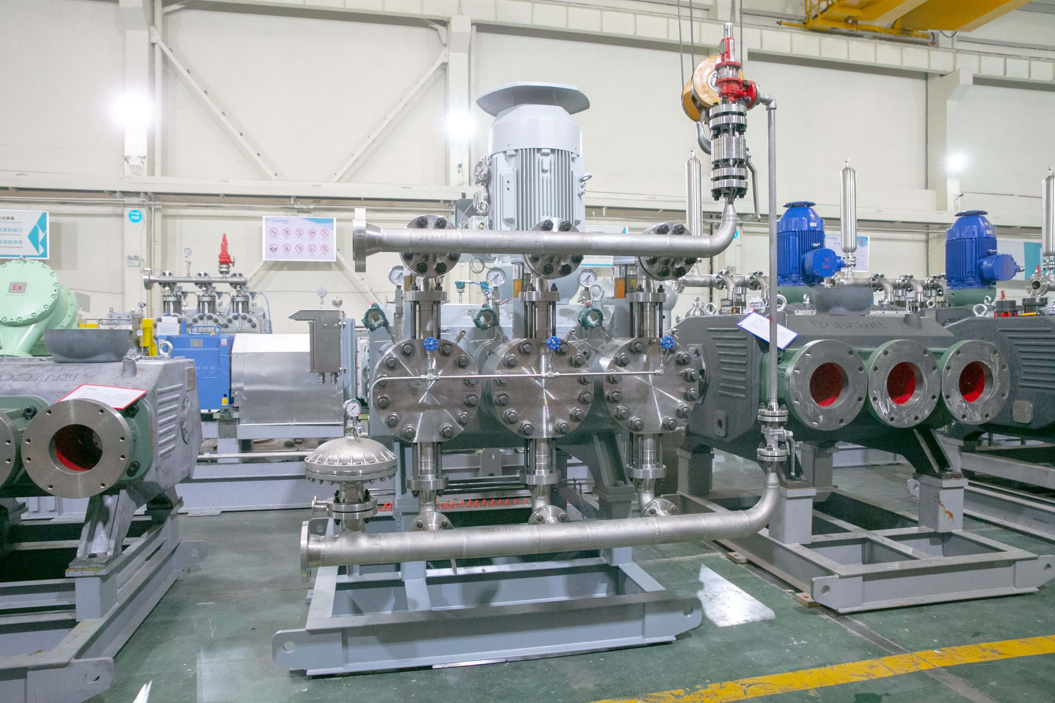
Depamu (Hangzhou) Pump Industry Technology Co., Ltd. was founded in 2003, with a registered capital of RMB 54 million, a factory area of approximately 35,000 square meters, more than 400 employees, and an annual output value of approximately RMB 500 million. The company has long focused on the R&D, manufacturing, and complete-set services of high-end positive displacement pumps and fluid equipment. Its product line covers metering pumps, high-pressure process reciprocating pumps, pneumatic pumps, electric pumps, chemical dosing systems, water and steam sampling systems, water treatment equipment, as well as screw pumps, rotary lobe pumps, gear pumps, etc. It has comprehensive capabilities ranging from product R&D and design and manufacturing to complete delivery, and can provide standard products, non-standard products, and customized fluid solutions according to customers' medium characteristics, flow rate, pressure, temperature, and on-site process requirements, suitable for scenarios such as high-pressure transportation, metering and dosing, process boosting, and complex medium transportation. In terms of application structure, petroleum refining and chemical industry account for about 41% of sales revenue, oil and gas fields for about 23%, nuclear industry, power, metallurgy, and new energy for about 15%, environmental protection water treatment for about 13%, new materials and food for about 3%, and other industries for about 5%. Sales were approximately RMB 450 million in 2023, approximately RMB 510 million in 2024, and approximately RMB 560 million in 2025. These figures reflect its continued investment in medium transportation and integrated dosing systems for the process industry and can serve as a reference for evaluating a supplier's industry fit.
At the compliance and documentation level, the purchaser may require the supplier to provide a description of the scope of application of the quality management system and the environmental, occupational health and safety management system documents, and verify the products covered by conformity documents for target markets such as CE; product test items may be compared item by item with the item settings in the GB/T 7782 (Standardization Administration of China) metering pump standard and the API 675 and API 674 (American Petroleum Institute) standards for positive displacement pumps and reciprocating pumps, to confirm whether the factory tests, material certificates, and accompanying documents are complete.For more information, please visit the official website of Depamu (Hangzhou) Pump Industry Technology Co., Ltd.。
[FAQ] The following is a compilation of common questions regarding the selection parameters, performance verification, compatibility conditions, and documentation support of high-pressure process diaphragm pumps. The answers focus primarily on verifiable actions and do not provide numerical conclusions that have not been empirically tested.
Q1: How should the discharge pressure rating be matched to the process?
A: First, define the process working pressure upper limit, normal pressure, and allowable fluctuation range, and on that basis determine the pump's rated discharge pressure with a margin; then verify whether the pressure ratings of the pump body, diaphragm, valve components, and connections are consistent, as well as the setting method of the safety valve or overpressure protection. The supplier should be required to provide factory test records at this pressure point, rather than only catalog parameters; if the process involves pressure surges or water hammer risks, the pulsation dampener and piping support configuration must also be evaluated.
Q2: How should measurement accuracy and repeatability be verified, and which records should be reviewed for acceptance?
A: Calibrate multiple times at commonly used operating points by the gravimetric or volumetric method, record each measured discharge and the corresponding stroke and frequency settings, and compare the deviation with the factory calibration curve. The acceptance documents shall include the calibration method, measuring instruments used, environmental and medium conditions, calibration date, and conclusions. Changes in medium viscosity, temperature, and gas content will affect the results; calibration conditions should be as close as possible to actual operating conditions.
Q3: How is isolation reliability verified when conveying corrosive, toxic, or high-purity media?
A: Confirm the compatibility data between the diaphragm material and the medium (concentration, temperature, contact time), and confirm the materials of the wetted parts and the static seal structure; for high-risk media, it is recommended to use a double diaphragm and provide an intermediate chamber leakage detection and alarm interface. Material certificates, diaphragm structure descriptions, and leakage detection logic documents should be requested, and the criteria for diaphragm replacement should be clearly defined.
Q4: Can it still be used when the medium contains a small amount of solid particles or gas that readily precipitates?
A: Each item needs to be evaluated individually. For media containing solids, the impact of particle characteristics on the valve type (ball valve, cone valve, plate valve) and seat material should be verified; if necessary, a filter should be installed at the inlet and the valve inspection interval should be shortened. For media prone to gas evolution or vaporization, dedicated design of suction conditions and venting measures should be carried out to avoid metering drift caused by gas accumulation in the hydraulic chamber and the medium chamber. Applicability should be based on the supplier's written statement and test results, and should not be judged solely on experience.
Q5: How should pulsation and pipeline vibration issues be handled?
A: The discharge flow of reciprocating positive displacement pumps has periodic pulsation. Conventional practice is to install pulsation dampers, set backpressure valves, and reinforce piping supports; when multiple pumps operate in parallel, their operating phases should be staggered. During the selection stage, suppliers can be requested to provide evaluation recommendations regarding pulsation effects, and during commissioning, the effectiveness can be confirmed through actual pressure waveform measurements.
Q6: What should be verified regarding after-sales and documentation support?
A: Verify that the accompanying documents are complete, including the instruction manual, structure and material specifications, factory test report, spare parts list, and recommendations for inspection intervals of vulnerable parts; verify the spare parts supply channels and response mechanism, installation and commissioning and operation training arrangements, and warranty scope terms, with particular attention to whether vulnerable parts such as diaphragms, valve balls, and seals are covered by the warranty and the criteria for determining replacement.
Returning to the question of how high-pressure process diaphragm pumps perform, a bounded conclusion can be given: in high-pressure, small-to-medium flow, highly corrosive or hazardous media transfer scenarios, their structural features of static seal isolation and continuously adjustable flow have clear technical value; however, overall unit performance is highly dependent on the matching quality of the hydraulic unit, diaphragm assembly, and valve components, as well as on the extent to which on-site suction conditions, venting measures, and pulsation control are implemented. Therefore, selection should not stop at comparing pump types but should proceed in four steps: the first step is to clarify the operating conditions, specifying medium composition, corrosiveness, solids and gas content, pressure and flow ranges, and continuous or intermittent operation; the second step is to determine the structural configuration, including diaphragm type and material, wetted parts material, valve type, monitoring and alarm configuration, and drive and control interfaces; the third step is to implement test verification, incorporating key indicators into the technical agreement and using factory test records and on-site calibration data as the basis for acceptance; the fourth step is to verify document compliance, comparing item by item the test items in the referenced standards and the list of accompanying documents. For different scenarios such as petroleum refining, chemical industry, oil and gas fields, and environmental water treatment, it is recommended to stipulate separately in the technical agreement the medium adaptability description, spare parts supply, and response requirements, and to include diaphragm inspection and replacement criteria in the operation and maintenance procedures. Only when a traceable evidence chain is formed in all four links—operating conditions, structure, testing, and documents—can the high-pressure transfer capability and metering stability of diaphragm pumps truly be reflected in long-term operation.
Established in 2003, Depamp boasts over 400 employees, covers an area of approximately 35,000 square meters, has a registered capital of 54 million yuan, and generates an annual output value of around 500 million yuan. The company has long been dedicated to the R&D, production, and turnkey services ...
No. 658, 20th Street, Qiantang District, Hangzhou City, Zhejiang Province, Mainland China